
Copper Heat Dissipation Material, Carrier-Attached Copper Foil, Connector, Terminal, Laminate, Shield Material, Printed-Wiring Board, Metal Processed Member, Electronic Device and Method for Manufacturing the Printed Wiring Board

a technology of heat dissipation material and printed wiring, which is applied in the direction of circuit precursor manufacturing, coupling device connection, metallic pattern materials, etc., can solve the problems that the liquid crystal frame conventional use, however, has failed to meet the function of dissipating heat from e.g., liquid crystal components and ic chips, and achieves satisfactory heat dissipation performance

Active Publication Date: 2016-04-28
JX NIPPON MINING& METALS CORP
View PDF13 Cites 28 Cited by
  • Summary
  • Abstract
  • Description
  • Claims
  • Application Information

AI Technical Summary

Benefits of technology

The present invention provides a copper heat dissipation material that has excellent heat dissipation performance.

Problems solved by technology

Due to the recent tendency of electronic devices described above, liquid crystal frames conventionally used, however, have failed to satisfy the function of dissipating heat from e.g., liquid crystal components and IC chips, such as transition heat, radiation heat and convection heat, outside so as not accumulate heat inside.

Method used


Image

  • Copper Heat Dissipation Material, Carrier-Attached Copper Foil, Connector, Terminal, Laminate, Shield Material, Printed-Wiring Board, Metal Processed Member, Electronic Device and Method for Manufacturing the Printed Wiring Board
  • Copper Heat Dissipation Material, Carrier-Attached Copper Foil, Connector, Terminal, Laminate, Shield Material, Printed-Wiring Board, Metal Processed Member, Electronic Device and Method for Manufacturing the Printed Wiring Board
  • Copper Heat Dissipation Material, Carrier-Attached Copper Foil, Connector, Terminal, Laminate, Shield Material, Printed-Wiring Board, Metal Processed Member, Electronic Device and Method for Manufacturing the Printed Wiring Board

Examples


examples 1 to 11 , 13 to 18

Examples 1 to 11, 13 to 18, Comparative Examples 1 to 8

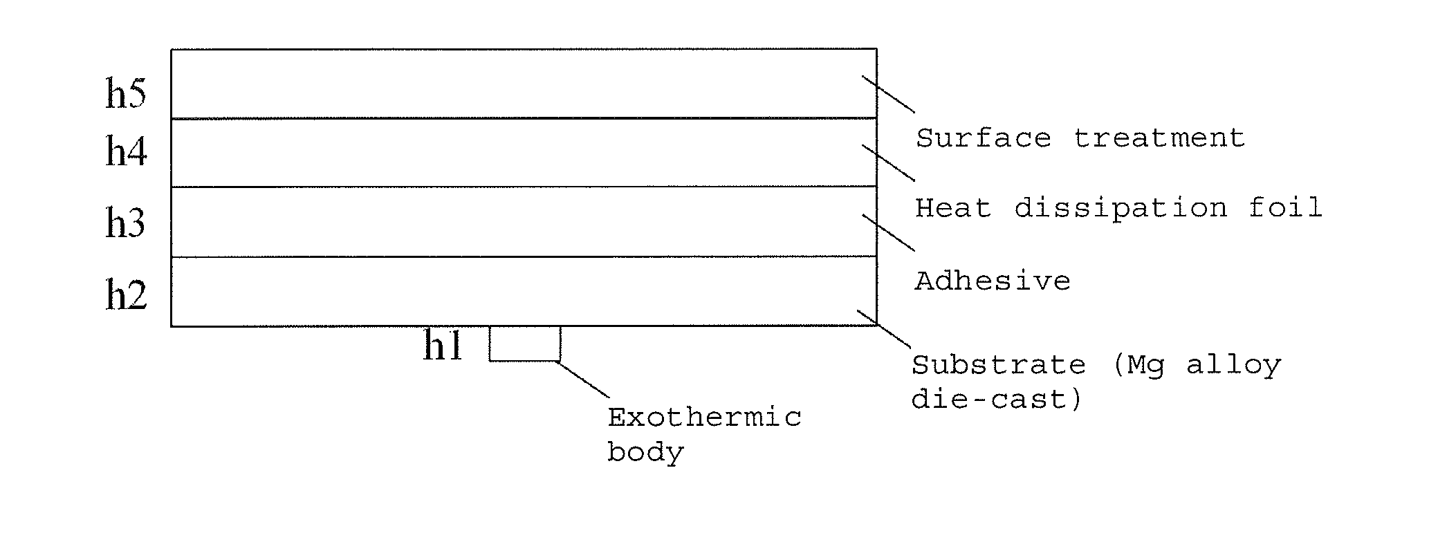
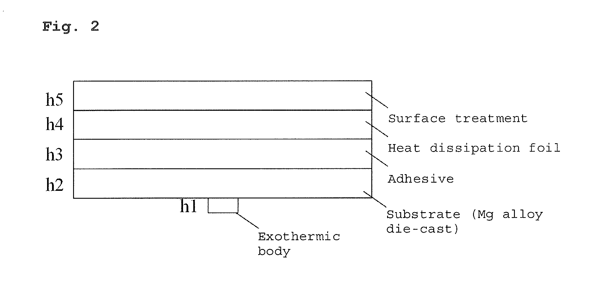
[0353]As Examples 1 to 11, 13 to 18 and Comparative Examples 1 to 8, various types of copper substrates having the thicknesses described in Tables 1 to 4 were prepared. Next, on each of the copper substrates, alloy layers were formed; more specifically, alloy layers (1) to (3) shown in Tables 1 to 4, were formed in this order.

example 12

[0354]As the substrate of Example 12, the following carrier-attached copper foil was prepared. First, an electrolytic copper foil, i.e., JTC foil (manufactured by JX Mining & Metals Corporation) having a thickness of 18 μm was prepared as a carrier. Then, an intermediate layer was formed on the glossy surface of the carrier in the following conditions and an ultra-thin copper layer was formed on the intermediate layer.

Intermediate Layer

[0355](1) Ni Layer (Ni Plating)

[0356]The carrier was electroplated on a roll-to-roll continuous plating line in the following conditions to form a Ni layer in an amount deposited of 1000 μg / dm2. The plating conditions are more specifically as follows.

[0357]Nickel sulfate: 270 to 280 g / L

[0358]Nickel chloride: 35 to 45 g / L

[0359]Nickel acetate: 10 to 20 g / L

[0360]Boric acid: 30 to 40 g / L

[0361]Gloss agent: e.g., saccharin, butynediol

[0362]Sodium dodecyl sulfate: 55 to 75 ppm

[0363]pH: 4 to 6

[0364]Bath temperature: 55 to 65° C.

[0365]Current density: 10 A / dm2...


PUM

PropertyMeasurementUnit
Nanoscale particle sizeaaaaaaaaaa
Surface roughnessaaaaaaaaaa

Abstract

A copper heat dissipation material having a satisfactory heat dissipation performance is provided. The copper heat dissipation material has an alloy layer containing at least one metal selected from Cu, Co, Ni, W, P, Zn, Cr, Fe, Sn and Mo on one or both surfaces, in which surface roughness Sz of the one or both surfaces, measured by a laser microscope using laser light of 405 nm in wavelength, is 5 μm or more.

Description

BACKGROUND OF THE INVENTION[0001]1. Field of the Invention[0002]The present invention relates to a copper heat dissipation material, a carrier-attached copper foil, a terminal, a laminate, a shield material, a printed-wiring board, a metal processed member, an electronic device and a method for manufacturing the printed wiring board.[0003]2. Description of the Related Art[0004]Recently, with the tendency toward miniaturization and high-definition of electronic devices, it has been concerned that the electronic devices break down with heat generated by the electronic components used therein. In particular, in electronic components used in electric cars and hybrid electric cars, which experience remarkable growth, there are components, such as connectors in the battery portion, through which significantly high current flows, and heat generated from the electronic components during current supply has been a matter of concern. In the meantime, in liquid crystals of smart phone tablets a...

Claims


Application Information

Patent Timeline
IPC IPC(8): H05K1/02H05K7/20H01R13/03B32B38/10B32B15/01B32B15/04B32B15/20H01L23/373B32B3/26
CPCH05K1/0203H01L23/3735H05K7/2039H01R13/03B32B3/263B32B15/01B32B2307/302B32B15/20B32B38/10B32B2255/06B32B2255/26B32B2457/00B32B15/043H05K1/0207H05K3/00H05K7/20954H05K2201/06H01L23/3736H01L2924/0002B32B37/02B32B2457/08H05K1/09H05K3/025H05K2201/0338H05K2201/0355H05K2201/0358B32B7/12B32B15/08B32B15/18B32B27/18B32B27/20B32B27/281B32B27/304B32B27/322B32B27/34B32B27/36B32B27/38B32B2255/205B32B2307/202B32B2307/538B32B2457/20B32B2457/202C25D3/12C25D3/38C25D7/0614C25D9/08C22C9/06Y02E60/10C04B37/021C04B2237/407C04B2237/706H01L2924/00C25D7/06H01M4/662H05K1/0204H05K3/108
Inventor MOMOI, HAJIMEMORIOKA, SATORUONO, TOSHIYUKIARAI, HIDETAFUKUCHI, RYOMIKI, ATSUSHI
Owner JX NIPPON MINING& METALS CORP
Learn More