Electrophoretic insulated glass unit

a technology of solar energy and insulated glass, applied in the direction of door/window protective devices, instruments, constructions, etc., can solve the problems of insufficient variable light transmittance solution of smart glass, limited functionality of available smart glass solutions, and inability to remove coatings from windows, etc., to achieve the effect of minimizing temperature build-up, maximizing thermal conductance of each layer, and minimizing thickness of each layer

Active Publication Date: 2016-05-05
E INK CORPORATION
View PDF2 Cites 33 Cited by
  • Summary
  • Abstract
  • Description
  • Claims
  • Application Information

AI Technical Summary

Benefits of technology

[0041]In embodiments said heat in said first light state is dissipated from said outer face by thermal radiation and convection, and said heat dissipates from said charged particles to said outer face by thermal conduction and thermal radiation, to minimize temperature build-up within layers between said charged particles and said outer face the thermal conductance of each layer is maximized and the thickness of each layer is minimized.
[0042]To maximize thermal conductance in embodiments the different polymer materials in layers have a thermal conductivity of 0.1 W / (m·K) or more, and preferably of 0.15 W / (m·K) or more, and more preferably of 0.2 W / (m·K) or more, and the thickness of said electrophoretic device's substrate is 200 micron or less, more preferably 175 micron or less, and most preferably 125 micron or less, and the thickness of an interlayer is 0.8 mm or less, more preferably 0.5 mm or less, and most preferably 0.38 mm or less (a preferred interlayer is the Sekisui S-LEC EN in 0.25 mm thickness), and the thickness of the outer pane (providing said outer face) is preferably 6 mm or less, more preferably 4 mm or less, and most preferably 2.6 mm or less.

Problems solved by technology

These coatings cannot be removed from a window when the function is not required unlike adjusting a mechanical blind.
The available smart glass solutions (also known as switchable windows) have limited functionality and inherent technological obstacles.
In the prior art of liquid crystal, smart glass there is no adequate variable light transmittance solution, or no solution offering selective control of solar transmittance.
SPD smart glass provides a variable light transmittance function (dimming while maintaining transparency) but does not provide privacy (not opaque or translucent), and does not provide active control over infrared (i.e. SPD devices do not reflect infrared light).
An inherent technological obstacle with SPD devices in the prior art is that their light absorptance is not neutral in the visible light range with the consequence that their dimming states appear somewhat blue and their fully darkened state appears dark blue.
Electrophoretic technology would seem to have the advantage of a black state but the prior art does not provide feasible solutions for smart glass.
But while the fine patterning of electrodes is normal for display devices having a matrix of pixels, it is prohibitively expensive for a device intended for smart glass applications.
The feasibility of these prior art electrophoretic technologies for smart glass applications is questionable due to the efficacy of their transparent light state or their complexity.
This would seem to limit such devices to small areas and discrete or batch manufacturing, and such tooling would not seem suited to the large-format, roll-to-roll manufacturing desirable for smart glass.
In general, the prior art of smart glass does not describe what happens this solar energy when it is absorbed by light states, does not provide the means to manage and adapt the visible light spectrum and the sunlight infrared spectrum for a climate, and does not provide solutions that direct the energy from absorbed sunlight to substantially an outside or inside environment as required.
Furthermore, the prior art of smart glass is largely silent with respect to managing the heat build-up within a device that absorbs incident solar energy.

Method used


Image

  • Electrophoretic insulated glass unit
  • Electrophoretic insulated glass unit
  • Electrophoretic insulated glass unit

Examples


example 1

Warm Climate Configuration Having a Coating with the Infrared Cut-Off Wavelength Adjacent the Thermal Radiation Spectrum

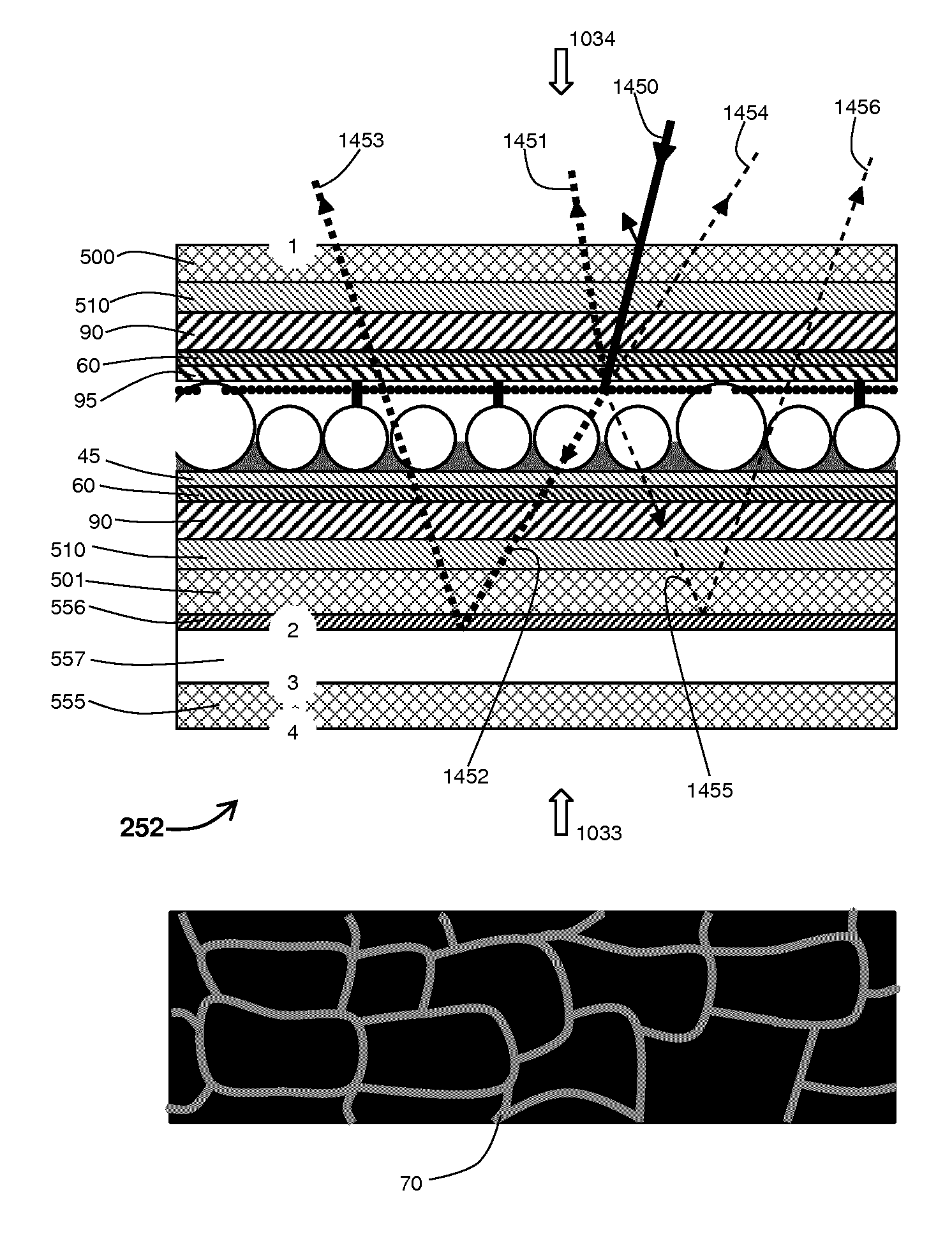
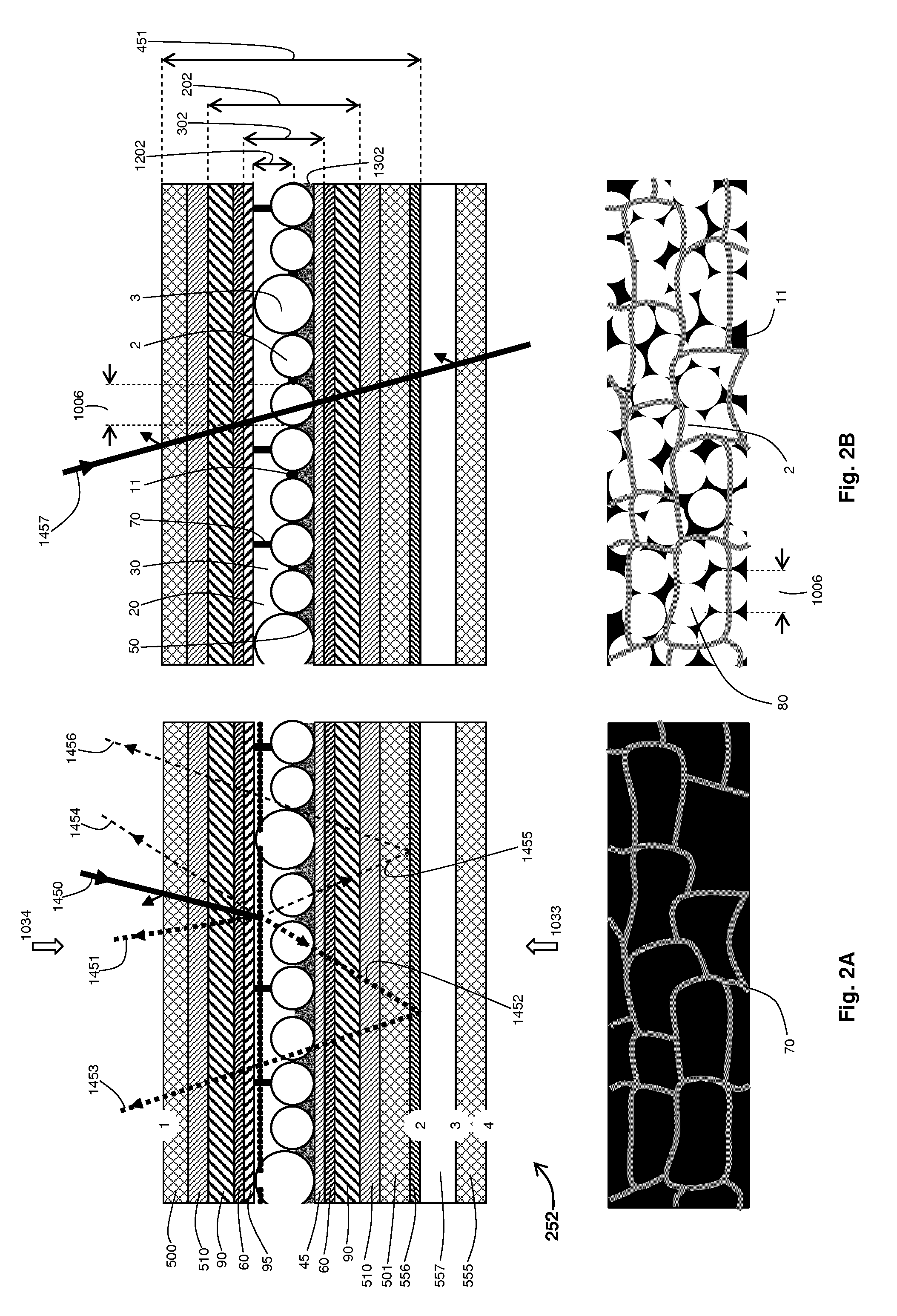
[0161]The following is an example of an embodiment 252, a configuration for moderate-to-hot climates, which maximizes the available range of SHGC (i.e. the SHGC range is up to twice that of embodiment 251). Embodiment 252 uses Pilkington (see www.pilkington.com) Energy Advantage OW, a pyrolytic-coated, low-emissivity, extra-clear glass as pane 501 of electrophoretic glass laminate 451 with the low-emissivity coating 556 on the number 2 surface (see FIG. 2A). The electrophoretic film 202 used in electrophoretic laminate 451 had a VLT of about 0.70. In a second light state the IGU embodiment 252 has a visible light transmittance of about 52.5%, a SHGC of about 0.48 (down from 0.69 for Energy Advantage OW in a passive IGU), and an LSG ratio of about 1.09 (the same as Energy Advantage OW in a passive IGU). In an intermediate light state IGU embodiment 252 has a visible...

example 2

Cold Climate Configuration Having a Coating with the Infrared Cut-Off Wavelength Adjacent the Thermal Radiation Spectrum

[0163]The following is an example of an IGU 253 that maximizes the solar energy transmitted to an inside environment using a configuration for cold climates. Embodiment 253 uses Asahi Glass Company (see www.agc.com) Planibel G fasT low-emissivity glass as pane 501 of electrophoretic glass laminate 451 with the low-emissivity coating 556 on the number 3 surface (see FIG. 3A). The electrophoretic film 202 used in electrophoretic laminate 451 had a VLT of about 0.70. The IGU embodiment has a SHGC of about 0.74 (the same as Planibel G fasT in a passive IGU) in all light states. In a second light state visible light transmittance is about 52.5%, and the LSG ratio is about 0.71 (down from 1.01 for Planibel G fasT in a passive IGU). In an intermediate light state visible light transmittance is 25%, and the LSG ratio is about 0.34. In another intermediate light state visib...

example 3

Hot Climate Configuration Having a Coating with the Infrared Cut-Off Wavelength Adjacent the Visible Spectrum

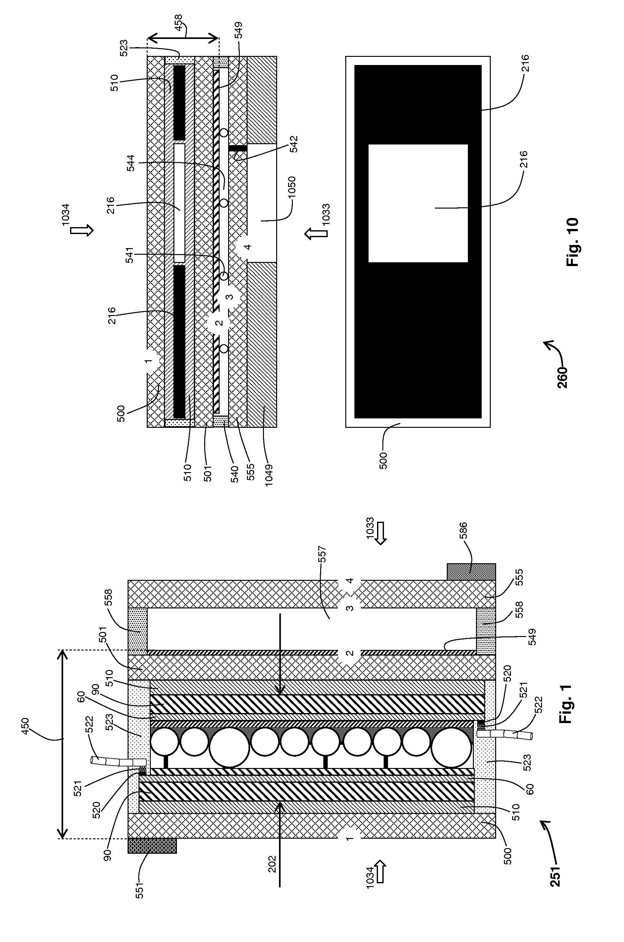
[0167]The following is an example of an embodiment 251, a configuration for hot climates, that minimizes solar heat transmitted to an inside environment 1033 while maximizing visible light transmitted (i.e. it demonstrates how an embodiment can maximize the LSG ratio). Embodiment 251 uses Asahi Glass Company's Planibel Energy NT spectrally selective glass (see www.yourglass.com) as pane 501 of electrophoretic glass laminate 450 with the spectrally selective coating 549 on the number 2 surface (see FIG. 4A). The electrophoretic film 202 used in glass laminate 450 had a VLT of about 0.70. In a second light state the IGU embodiment 251 has a visible light transmittance of about 52.5%, a SHGC of about 0.32 (down from 0.45 for Planibel Energy NT in a passive IGU), and an LSG ratio of about 1.67 (the same as Planibel Energy NT in a passive IGU). In an intermediate light state IGU e...


PUM

PropertyMeasurementUnit
cut-off wavelengthaaaaaaaaaa
transmittanceaaaaaaaaaa
wavelengthaaaaaaaaaa

Abstract

An electrophoretic insulated glass unit (IGU) comprises an electrophoretic laminate and a pane spaced apart from the electrophoretic laminate, the respective inner faces of the laminate and the pane defining a sealed cavity there between. An outer face of the electrophoretic laminate is in contact with an environment. One inner face of the cavity has a coating that is transparent to visible light and which rejects infrared light greater than a cut-off wavelength. The electrophoretic laminate includes an electrophoretic device including charged particles of at least one type in an electrophoretic cell, the particles being responsive to an electric field applied to the electrophoretic device to move between: a first extreme light state in which particles are maximally spread within the cell to lie in the path of sunlight through the cell and to strongly absorb visible sunlight transmitted through the cell and a second extreme light state in which the particles are maximally concentrated within the cell to remove them from the path of sunlight through the cell and to substantially transmit visible sunlight through the cell. The coating is arranged to direct thermal radiation emitted by the charged particles to the environment in contact with the outer face, and the sealed cavity is arranged to direct thermal conduction diffusing from the charged particles to the environment in contact with the outer face.

Description

RELATED APPLICATIONS[0001]The present application relates to Irish Patent Application No. S2013 / 0104 titled “An Electrophoretic Device Having a Transparent Light State” filed on 22 Mar. 2013 (attorney reference P106878IE00); and co-filed Irish Patent Application No. S2013 / 0181 titled “Solar Control Device, Medium and Ink” (attorney reference P107545ie00 ).FIELD[0002]The present invention relates to an electrophoretic solar control device that is in the form of an insulating glass unit.BACKGROUND TO THE INVENTION[0003]It is desirable to electronically control solar transmittance in windows to regulate solar heating and sunlight illumination. The sunlight spectrum is made up of an ultra-violet spectrum, a visible light spectrum, and a sunlight infrared spectrum. Generally it is desirable for windows to reject or filter the sunlight ultra-violet spectrum. Preferably, an electronic solution's visible-light functionality would include that provided by mechanical blinds or curtains; for e...

Claims


Application Information

Patent Timeline
Patent Type & Authority Applications(United States)
IPC IPC(8): G02F1/167G02B5/28G02F1/1675
CPCG02F1/167G02F2001/1678G02B5/282E06B2009/2464E06B9/24E06B2009/2417E06B2009/2423G02F1/1675
Inventor O'KEEFFE, DONAL
Owner E INK CORPORATION
Why Eureka
Try Eureka