Fuel cell system and control method therefor

a fuel cell and system technology, applied in the field of fuel cell systems, can solve the problems of giving the user a sense of discomfort or a sense of incompatibility, anxiety, and the residing water of the fuel, and achieve the effects of suppressing abnormal noise, reducing discomfort or a sense, and reducing the generation of abnormal nois

a fuel cell and system technology, applied in the field of fuel cell systems, can solve the problems of giving the user a sense of discomfort or a sense of incompatibility, anxiety, and the residing water of the fuel, and achieve the effects of suppressing abnormal noise, reducing discomfort or a sense, and reducing the generation of abnormal nois

US20160141656A1Active Publication Date: 2016-05-19TOYOTA JIDOSHA KK

Image

  • Fuel cell system and control method therefor
  • Fuel cell system and control method therefor
  • Fuel cell system and control method therefor

Examples


modification examples

B. Modification Examples

(1) Modification Example 1

[0102]With the embodiment above, the fuel cell 10 is a so-called “counter-flow” type. However, this invention is not limited to that type, and a so-called “co-flow” type or so-called “cross-flow” type fuel cell may be employed.

modification example 2

(2) Modification Example 2

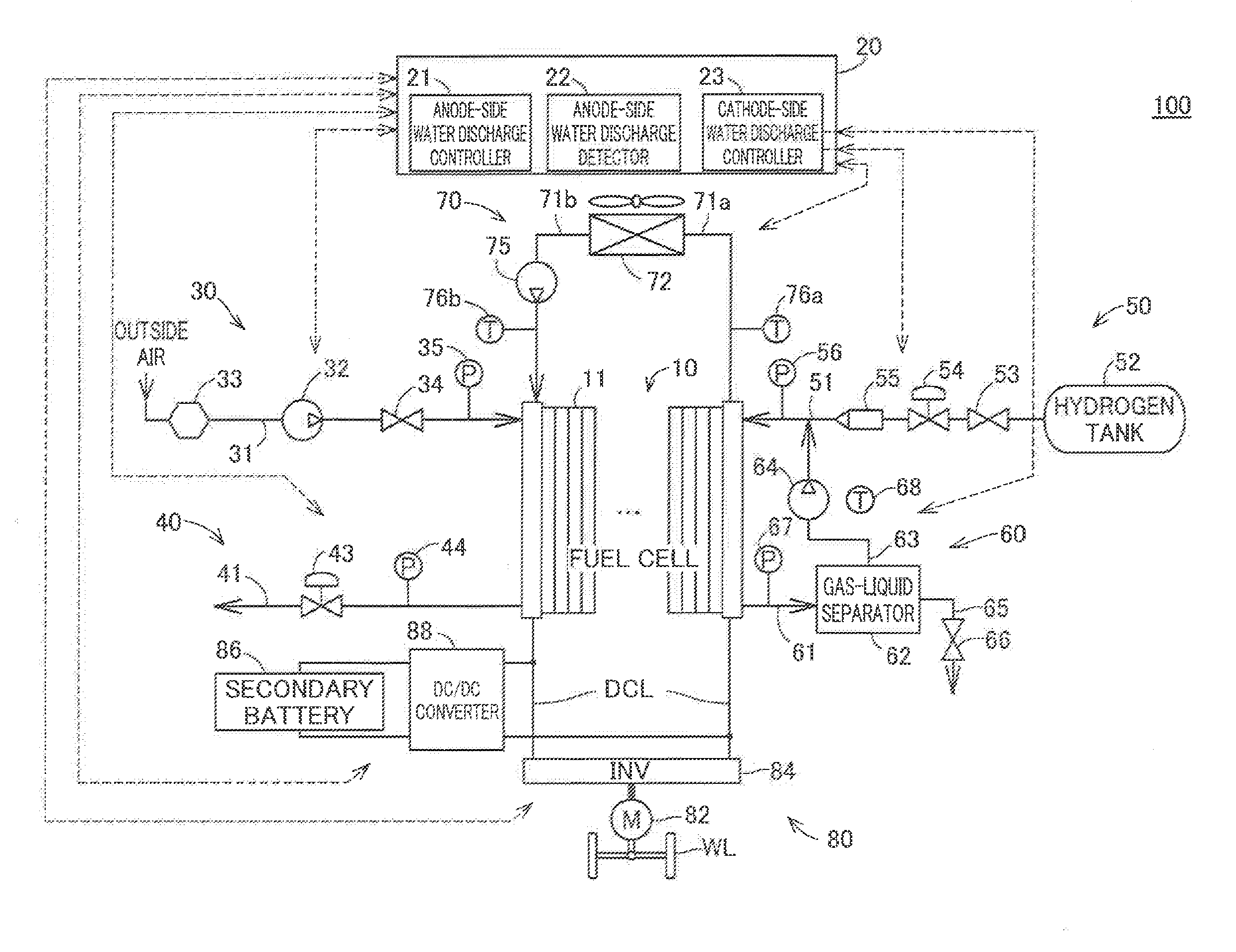
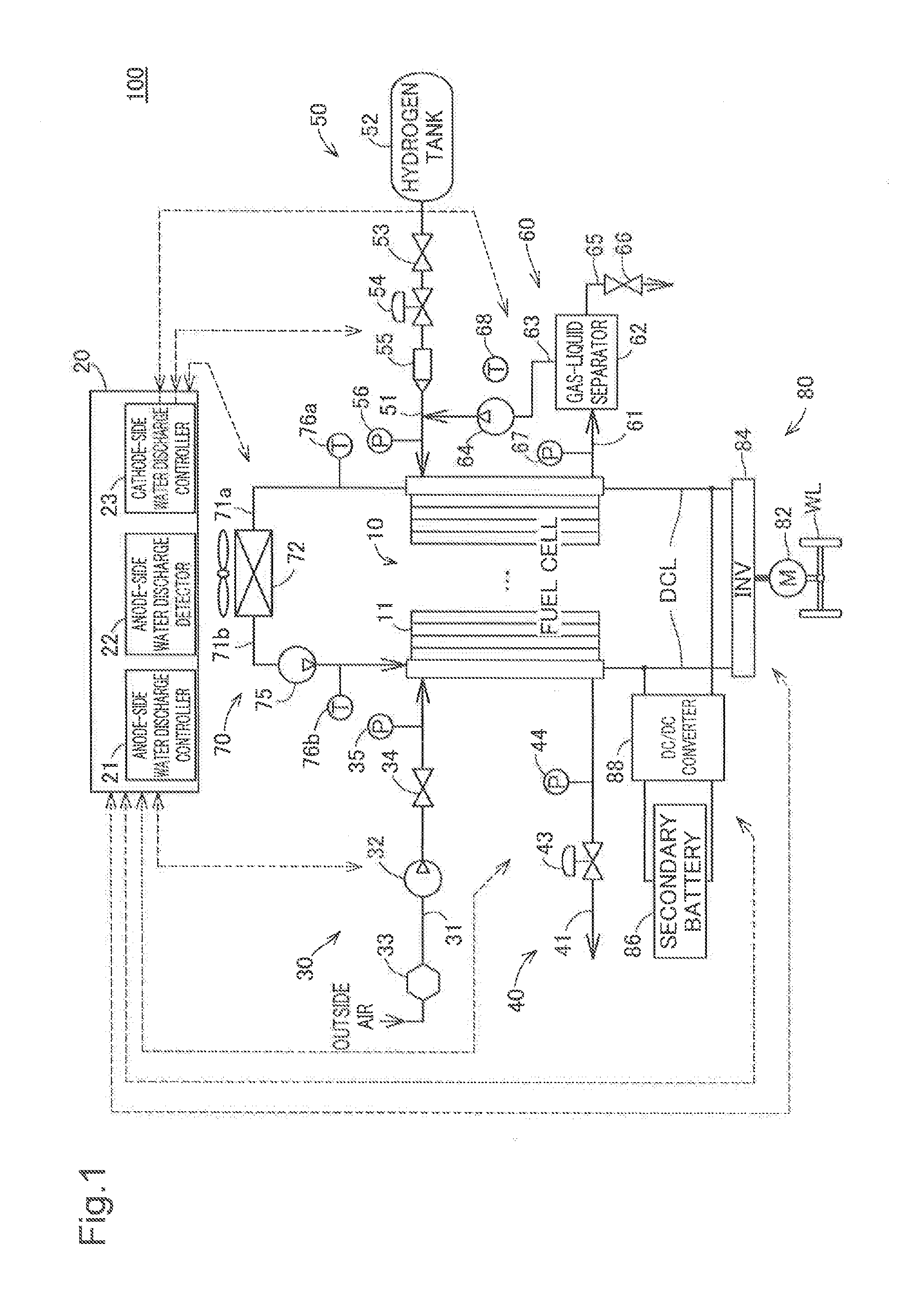
[0103]With the embodiments above, the controller 20 is a microcomputer and described as having a configuration that is able, by running the software that corresponds to a variety of controls, is able to carry out the functions of the overall controller, the cathode gas controller that controls the cathode gas supply system 30 and the cathode gas discharge system 40, the anode gas controller that controls the anode gas supply system 50 and the anode gas circulation system 60, the coolant controller that controls the coolant circulation system 70, the anode-side water discharge controller 21, the anode-side water discharge detector 22 and the cathode-side water discharge controller 23. However, the controller 20 may also be realized through the hardware configuration of each controller using dedicated processing circuitry.

modification example 3

(3) Modification Example 3

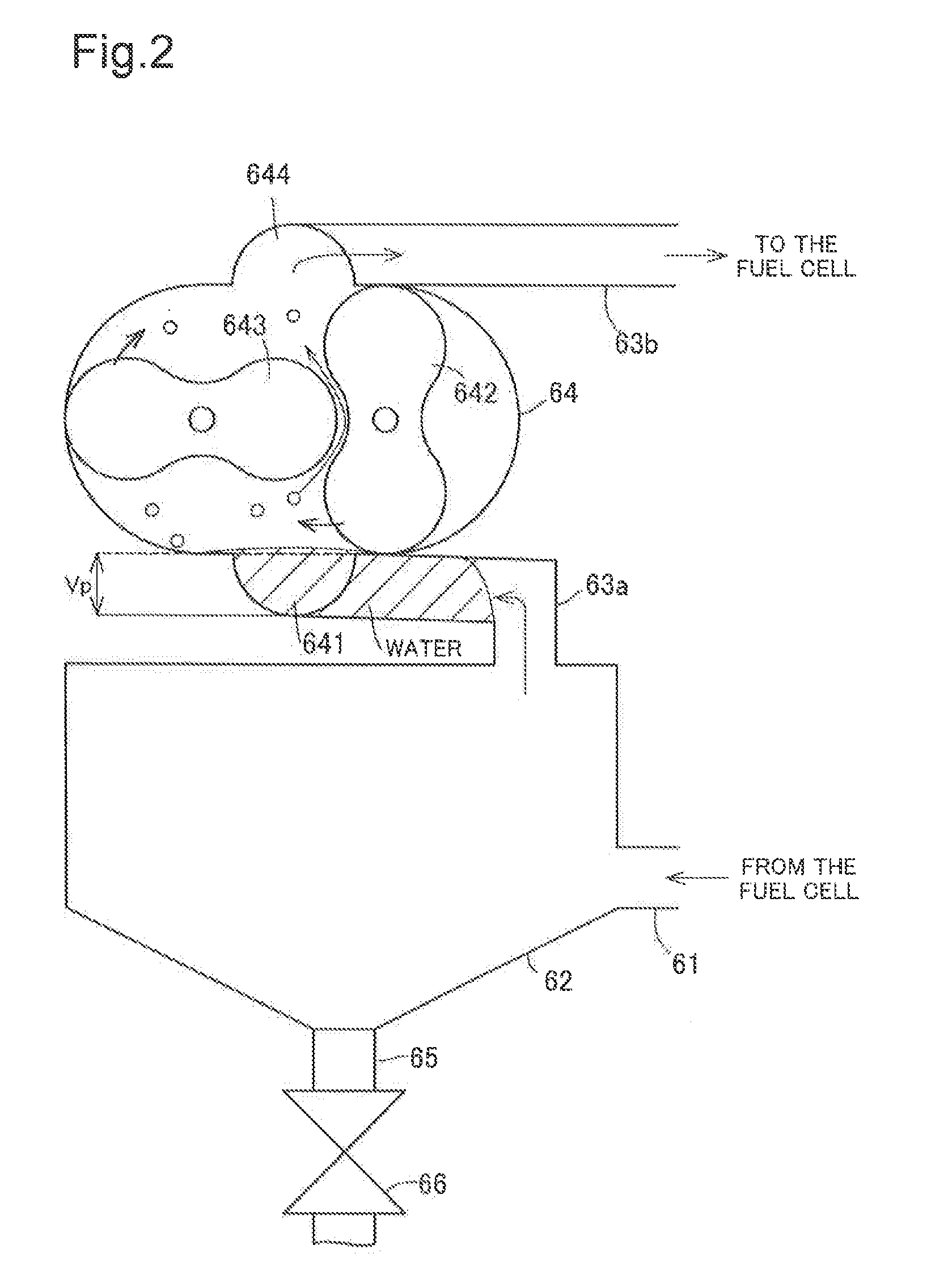
[0104]With the embodiment above, the retention time Tr, which corresponds to the ratio of the amount of residing water vis-à-vis the full-water volume at the suction port 641 of the hydrogen circulation pump 64, is employed. When that retention time Tr becomes 1 or more, the amount of residing water is determined to be at the full-water level and the anode-side forced water discharge process is executed. However, the present invention is not limited thereto, and it is also possible to execute anode-side forced water discharge process upon the determination of the full-water level by calculating the residing water in accordance with the circulation flow rate history (time changes) with the non-water-dischargeable rotational speed (An intermittent operation rotational speed).


PUM

PropertyMeasurementUnit
temperatureaaaaaaaaaa

Abstract

There are provided a an anode-side water discharge controller that controls a circulation flow rate of the anode gas pump so as to discharge anode-side liquid water residing in the anode-side flow path, and a cathode-side water discharge controller that controls a supply flow rate of the cathode gas pump so as to discharge cathode-side liquid water residing in the cathode-side flow path. The anode-side water discharge controller and the cathode-side water discharge controller execute water discharge by running a pre-selected one of the anode gas pump and the cathode gas pump, and then running the other of the anode gas pump and the cathode gas pump.

Description

CROSS-REFERENCE TO RELATED APPLICATIONS[0001]This application claims priority based on Japanese Patent Application No. 2014-231195 filed on Nov. 14, 2014, all of the disclosures of which are incorporated herein by reference.BACKGROUND[0002]1. Field[0003]The present invention relates to a fuel cell system and a control method therefor.[0004]2. Related Art[0005]Regarding a fuel gas supply system for supplying a fuel gas (hydrogen) to an anode of a fuel cell (fuel cell stack), there has conventionally been developed a fuel cell system in which fuel gas that has not been consumed by the anode of the fuel cell is circulated to the fuel gas supply system via a circulation pump of a fuel gas circulation system. As an example of this fuel cell system having a fuel gas circulation system, it is disclosed in JP2007-115460A that liquid water condensed on a pipe inner wall of a fuel gas circulation system is discharged by increasing the rotation speed of the circulation pump so as to reduce the...

Claims


Application Information

Patent Timeline
19 May 2016
Publication
US20160141656A1
IPC
H01M8/04
CPC
H01M8/04156; H01M8/04097; H01M8/04111; H01M2250/20; H01M8/04828; H01M8/04992; H01M8/04388; H01M8/04291
Inventors
YAMAMOTO, KAZUO; IMANISHI, HIROYUKI