Low temperature solid oxide cells

a technology of solid oxide cells and low temperature, which is applied in the direction of cell components, sustainable manufacturing/processing, instruments, etc., can solve the problems of increasing the cost of solid oxide fuel cells, the cost of certain applications of exotic materials, and the explosion of the array of materials now available to construct these cells

Active Publication Date: 2016-05-26
FCET
View PDF3 Cites 16 Cited by
  • Summary
  • Abstract
  • Description
  • Claims
  • Application Information

AI Technical Summary

Problems solved by technology

Also, the array of materials now available to construct these cells has exploded, since exotic and expensive high-temperature materials are no longer required.
The need for exotic materials greatly increases the costs of solid oxide fuel cells, making their use in certain applications cost-prohibitive.
Fourth, a lower operating temperature increases the service life of the cell.
Significantly, the high operating temperature is required because of poor low temperature ion conductivity.
However, high proton conductivity requires precise control of hydration in the electrolyte.
If the electrolyte becomes too dry, proton conductivity and cell voltage drop.
If the electrolyte becomes too wet, the cell becomes flooded.
Electro-osmotic drag complicates hydration control: protons migrating across the electrolyte “drag” water molecules along, potentially causing dramatic differences in hydration across the electrolyte that inhibit cell operation.
As a result, PEM cells are perhaps 40% less efficient than solid oxide fuel cells.
In conventional electrolyzers, electrical energy is lost in the electrolysis reaction driving the diffusion of ions through the electrolyte and across the distance between the electrodes.
However, at higher temperatures, electrolyzers face similar thermal stresses and cracking caused by differences in coefficients of thermal expansion between components of the solid oxide electrolyzer cell.
Moreover, given the high operating temperature of lambda sensors and similar devices, sensors face thermal stresses, cracking, and delamination issues similar to those facing fuel cells and electrolyzers.
However, epitaxially-grown STO and YSZ require an extraordinarily clean environment and a relatively small scale, in addition to expensive deposition equipment.
Furthermore, the geometries of establishing ionic communication between an electrode and an interface present another obstacle: the region for harvesting ions at the intersection of three materials (electrode, STO, and YSZ, for example) is by definition small compared to the contact area possible between an electrode and an electrolyte.
Moreover, the efficiency losses due to the thickness of electrolytes make thinner electrolytes desirable.

Method used


Image

  • Low temperature solid oxide cells
  • Low temperature solid oxide cells
  • Low temperature solid oxide cells

Examples


example 1

Electrolyte on Glass Substrates

[0211]Forty glass microscope slides measuring 1″×3″ (Ted Pella, Inc.) were obtained. Each slide was dipped into a composition containing yttrium carboxylates and zirconium carboxylates (2-ethylhexanoates) having a metal concentration of about 1 g / kg, and 15% atomic percent yttrium, withdrawn, heated to 420 to 450° C. in air and allowed to cool, thereby forming a single layer of yttria-stabilized zirconia (“YSZ”) on both sides of the glass. Then, the slides were dipped in a composition containing platinum (II) 2,4-pentanedionate in chloroform (Alfa Aesar), having 1 g Pt / kg composition diluted with 2-ethylhexanoic acid, withdrawn, heated to 420 to 450° C., and allowed to cool. The glass slides now had a layer of platinum oxide over a layer of yttria-stabilized zirconia on both planar sides of the glass.

example 2

Assembling Substrates with Spacer Elements

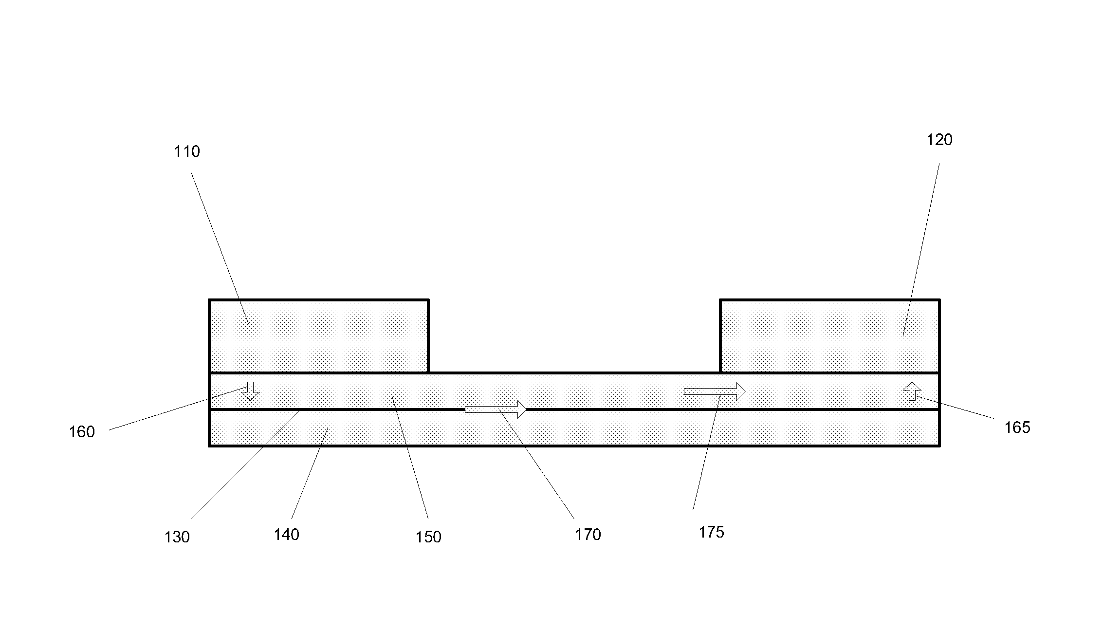
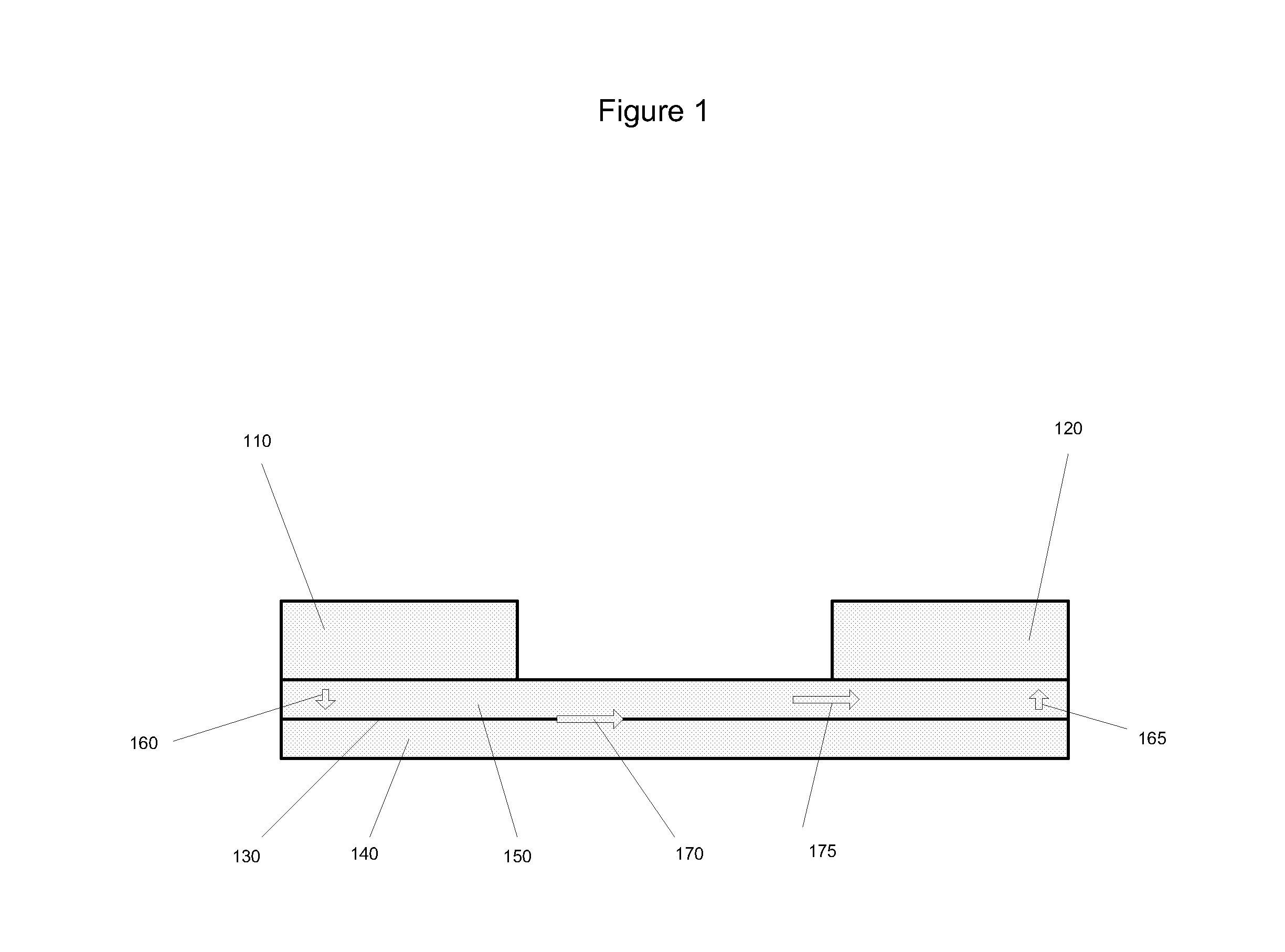
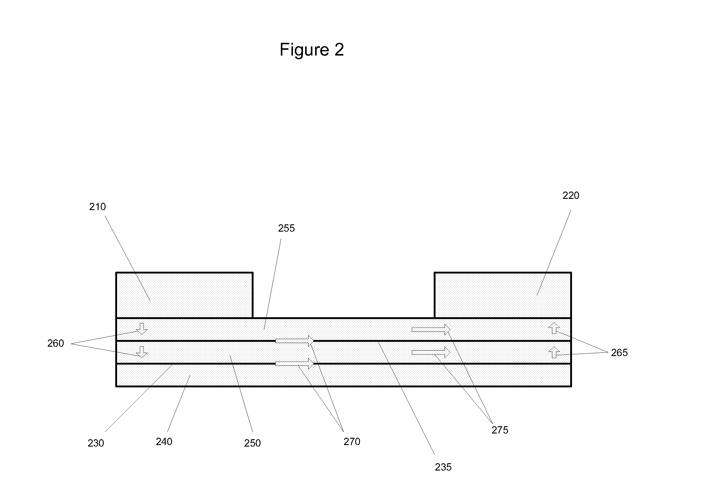
[0212]The electrolyte-coated substrates prepared in Example 1 were stacked together, each slide separated from the one below by two parallel strips of ceramic paper (McMaster) measuring 3″ long by 2 mm wide and about 0.5 mm thick. The ceramic paper spacer elements were saturated with high temperature pipe thread sealant (McMaster). Thus, the substrates and the ceramic paper spacer elements formed three passages, two side passages (“first passages”) and a central passage (“second passage”). The assembled substrates were compressed together in a rig similar to the one depicted in FIG. 7, heated in an oven set to 200° C. for one hour, and allowed to cool, whereupon it was observed that the electrolyte and the ceramic paper had bonded with the sealant.

example 3

Forming Electrodes

[0213]The assembled substrates with electrolyte were placed in a vacuum vessel with the substrates and ceramic paper spacer elements perpendicular to the horizontal, thereby exposing the passages defined by the substrates and the ceramic paper. An electrode composition containing platinum (II) 2,4-pentanedionate in chloroform (Alfa Aesar) (12 g Pt / kg, about 8% by weight of final electrode composition), yttrium carboxylates and zirconium caboxylates (30 g metal / kg, 15% atomic percent yttrium, about 8% by weight of final electrode composition), nickel flakes coated with silver (45% by weight of final electrode composition), nickel spheres coated with silver (30% by weight of final electrode composition), colloidal silver (Ted Pella) (about 8% by weight of final electrode composition), was poured over assembled substrates into the passages. The vacuum vessel was closed and a vacuum was drawn until the electrode composition began to boil. The assembly was removed and h...


PUM

PropertyMeasurementUnit
temperatureaaaaaaaaaa

Abstract

The present invention provides solid oxide cells such as fuel cells, electrolyzers, and sensors comprising an electrolyte having an interface between an yttria-stabilized zirconia material and a glass material, in some embodiments. Other embodiments add an interface between a platinum oxide material and the yttria-stabilized zirconia material in the electrolyte. Further embodiments of solid oxide cells have an ion-conducting species such as an ionic liquid or inorganic salt in contact with at least one electrode of the cell. Certain embodiments provide room temperature operation of solid oxide cells.

Description

RELATED APPLICATIONS[0001]This international application claims benefit of priority of U.S. Provisional Patent Application No. 61 / 846,411, entitled, “LOW TEMPERATURE SOLID OXIDE CELLS,” filed on Jul. 15, 2013; and U.S. Provisional Patent Application No. 61 / 857,856, entitled, “LOW TEMPERATURE SOLID OXIDE CELLS,” filed on Jul. 24, 2013; both of which applications are incorporated herein by reference in their entireties.FIELD OF INVENTION[0002]This invention relates to solid oxide cells that can operate at relatively low temperature. Solid oxide cells include solid oxide fuel cells, solid oxide electrolyzer cells, solid oxide sensors, and components of any of the foregoing.BACKGROUND OF THE INVENTION[0003]Unexpectedly, Applicants have invented ways to improve the performance of solid oxide cells at lower temperatures with certain embodiments of the present invention. In certain other embodiments, Applicants have achieved heretofore unknown room-temperature operation of solid oxide cell...

Claims


Application Information

Patent Timeline
Patent Type & Authority Applications(United States)
IPC IPC(8): H01M8/1007H01M8/1016C25B9/19
CPCH01M8/1007H01M2300/0071H01M8/1016H01M8/1009H01M8/1097H01M8/1213H01M8/1253H01M8/1286H01M8/2455H01M4/9016H01M4/9025H01M4/905H01M4/92H01M8/04186H01M2008/1293H01M2300/0002H01M2300/002H01M2300/0077H01M2300/0094G01N27/4073C25B15/02C25B15/08C25B1/46Y02E60/50Y02P70/50C25B9/19H01M8/2483H01M8/2432
Inventor POZVONKOV, MIKHAILDEININGER, MARK A.
Owner FCET
Why Eureka
Try Eureka