Liquid redistributor

a liquid redistributor and liquid technology, applied in liquid degasification, separation processes, carburetor air, etc., can solve the problems of foam formation, impaired operability of the column, and insufficient flow of process media through the column, so as to achieve the effect of increasing the output of the column

Active Publication Date: 2016-06-02
LAIR LIQUIDE SA POUR LETUDE & LEXPLOITATION DES PROCEDES GEORGES CLAUDE
View PDF2 Cites 4 Cited by
  • Summary
  • Abstract
  • Description
  • Claims
  • Application Information

AI Technical Summary

Benefits of technology

[0022]When carrying out this method, without use of the droplet damping trays according to the invention, gamma scanning of the column provided indications that a formation of foam might have occurred on the liquid distributor trays. When using the trays according to the in

Problems solved by technology

This fluidization can result in the formation of foam on the liquid layer, whereby the flux of the process media through the column and hence the operability of the column is

Method used


Image

  • Liquid redistributor
  • Liquid redistributor
  • Liquid redistributor

Examples


Embodiment Construction

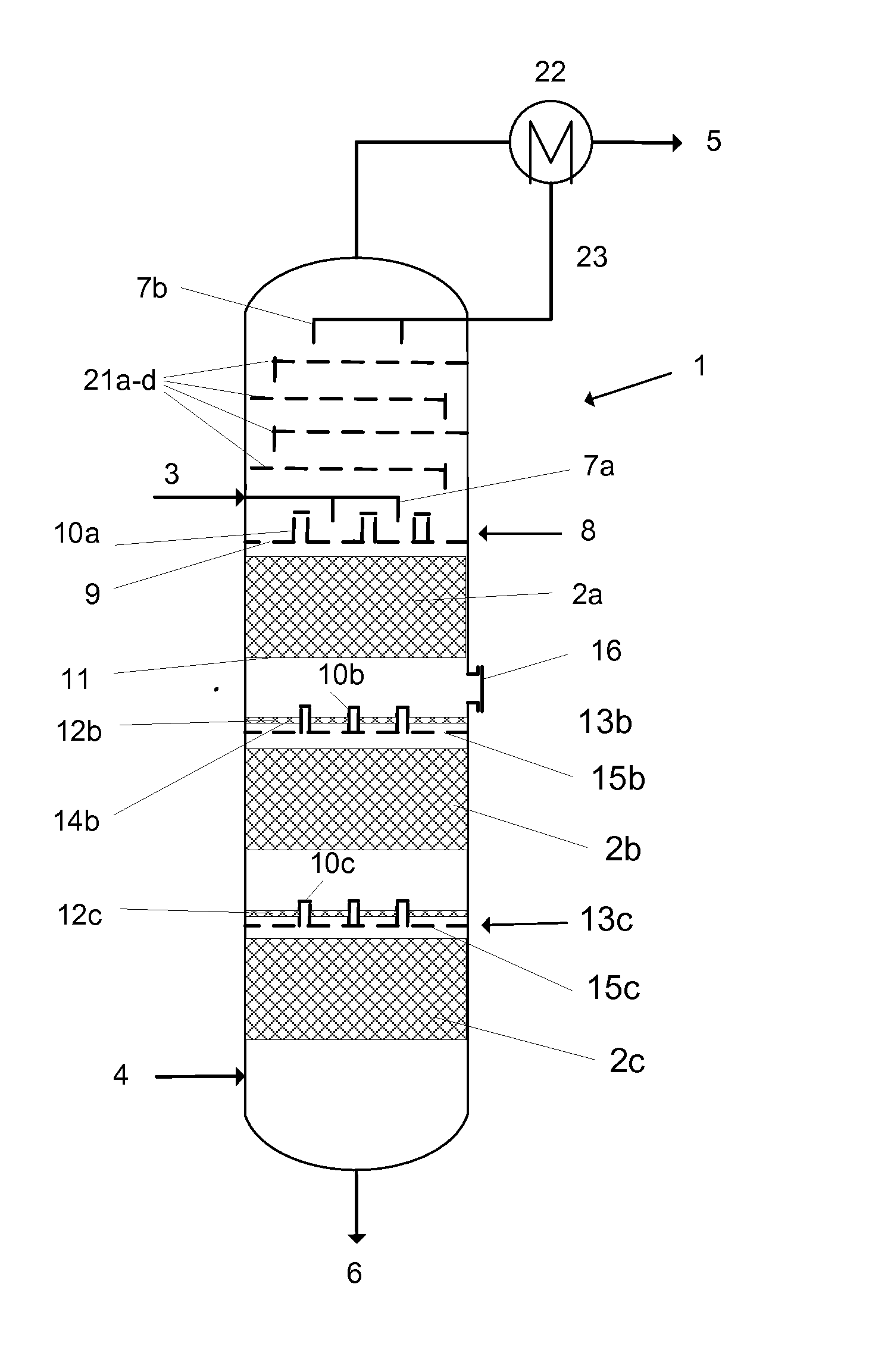
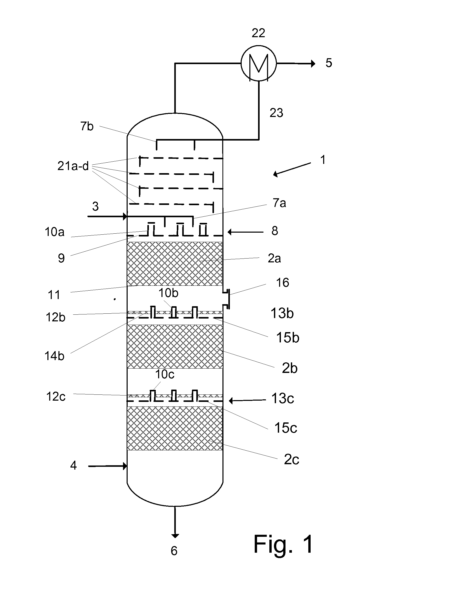
[0027]In FIG. 1, the column 1 in the lower part is designed as packing column with three packings 2a, b and c, and in the upper part as tray column with four wash trays 21a-d and a reflux condenser 22. The number of the packings and trays here is chosen by way of example, and it does not necessarily correspond to the number used in practice. Via conduit 3 the solvent as liquid phase and via conduit 4 the gaseous C4-hydrocarbon mixture as gas phase is introduced into the column. Via conduit 5 the refined product, i.e. the C4-hydrocarbon mixture liberated from 1,3-butadiene, and via conduit 6 the liquid product stream, i.e. the solvent loaded with 1,3-butadiene, is discharged from the column.

[0028]Via a feed system 7a, the solvent 3 is distributed on the liquid distributor 8 as uniformly as possible over the cross-section of the column 1. In the example shown here, the liquid distributor comprises a perforated plate 9 and gas chimneys 10a. In this example, it is not equipped with a dr...


PUM

PropertyMeasurementUnit
Heightaaaaaaaaaa
Heightaaaaaaaaaa
Distanceaaaaaaaaaa

Abstract

A liquid redistributor, arranged in a packing column between two packings, wherein in the column a liquid phase is guided from top to bottom and against the same a gas phase from bottom to top, comprising a liquid distributor tray and a droplet damping tray, which attenuates the fluidization of the liquid layer on the liquid distributor tray as caused by the droplets falling down.

Description

CROSS REFERENCE TO RELATED APPLICATIONS[0001]This application is a §371 of International PCT Application PCT / EP2014 / 064465, filed Jul. 7, 2014, which claims the benefit of DE 10 2013 107 357.3, filed Jul. 11, 2013, both of which are herein incorporated by reference in their entireties.FIELD OF THE INVENTION[0002]Embodiments of the invention relate to a liquid redistributor, arranged in a packing column, comprising a liquid distributor tray; furthermore, embodiments of the invention relate to packing columns which are equipped with at least one liquid redistributor. The term packing column here also comprises those columns, which e.g., are designed as packing columns only in their lower part, while their upper part is designed, e.g., as tray column. Furthermore, embodiments of the invention relate to a method for the extraction of 1,3-butadiene from a gaseous C4 hydrocarbon mixture, in which such packing columns are used.BACKGROUND[0003]To achieve a high separation efficiency of a pa...

Claims


Application Information

Patent Timeline
IPC IPC(8): B01D53/18B01D3/00B01J19/32B01D53/14
CPCB01D53/185B01J19/32B01D3/008B01D53/1487
Inventor ECK, THOMASKIRSTEN, KLAUS
Owner LAIR LIQUIDE SA POUR LETUDE & LEXPLOITATION DES PROCEDES GEORGES CLAUDE
Why Eureka
Try Eureka