Inductive rotary joint with multimode inverter

a multi-mode inverter and rotary joint technology, applied in the direction of dc-ac conversion without reversal, inductance, tomography, etc., can solve the problems of insufficient inductive coupling of rotary joints, large stress or even overload of associated electronic components, and high power contactors that are required for switching over input signals. , to achieve the effect of improving dynamic range, avoiding large inrush current, and increasing output power

Active Publication Date: 2016-06-23
SCHLEIFRING GMBH
View PDF2 Cites 15 Cited by
  • Summary
  • Abstract
  • Description
  • Claims
  • Application Information

AI Technical Summary

Benefits of technology

[0009]Embodiments of the invention provide a contactless inductively coupled rotary joint, which has a hardware safety circuit for delivering at least two different output power levels without requiring a high power contactor at the input side. A further problem to be solved is to provide an induc

Problems solved by technology

The disadvantage is that high power contactors are required for switching over the input signal.
A general problem exists in all mentioned inductively-coupled rotary joints when switching the output power on.
This may lead to a significant stress or even overload of associated electronic components.
A further problem to be so

Method used


Image

  • Inductive rotary joint with multimode inverter
  • Inductive rotary joint with multimode inverter
  • Inductive rotary joint with multimode inverter

Examples


Embodiment Construction

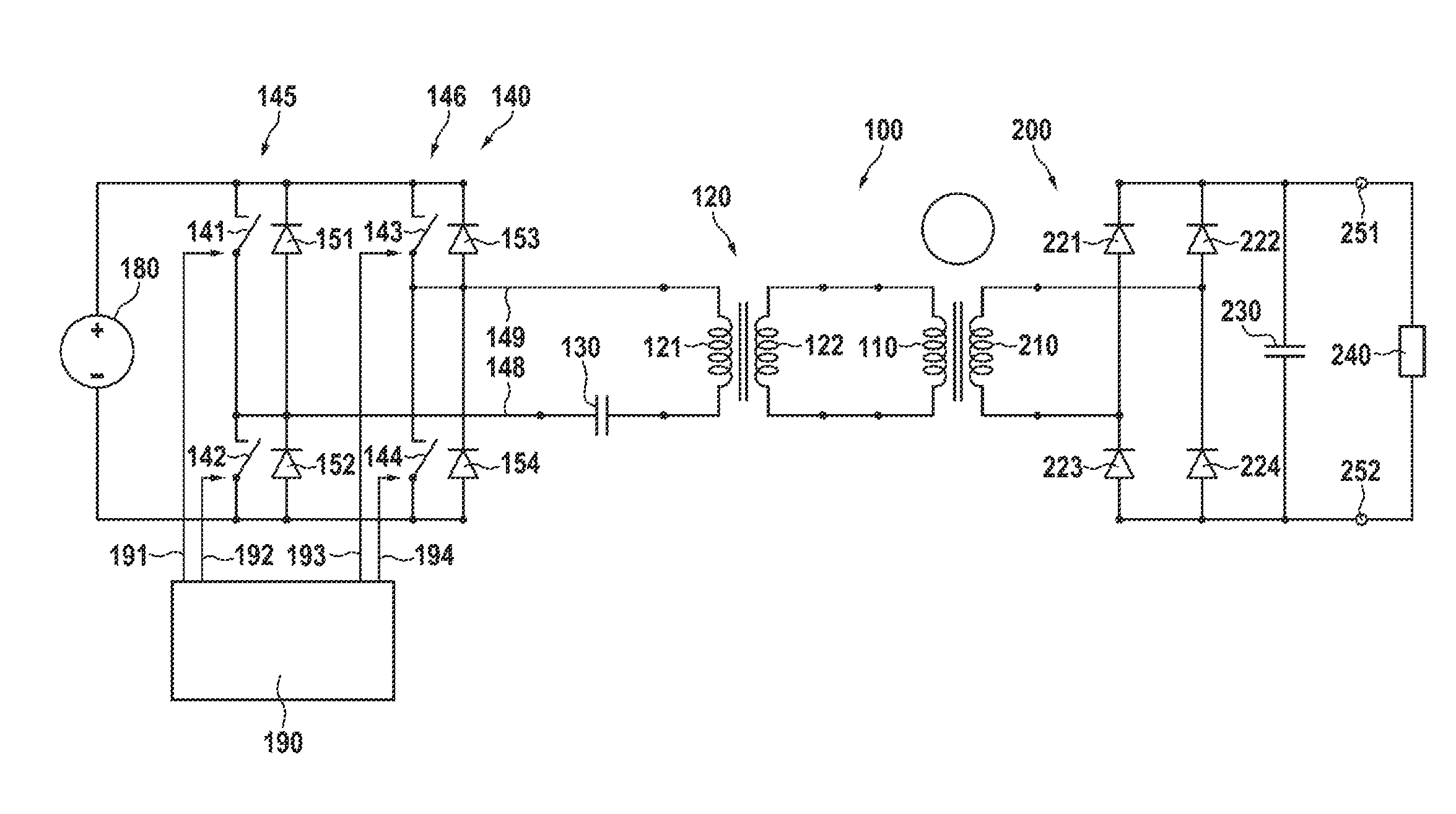
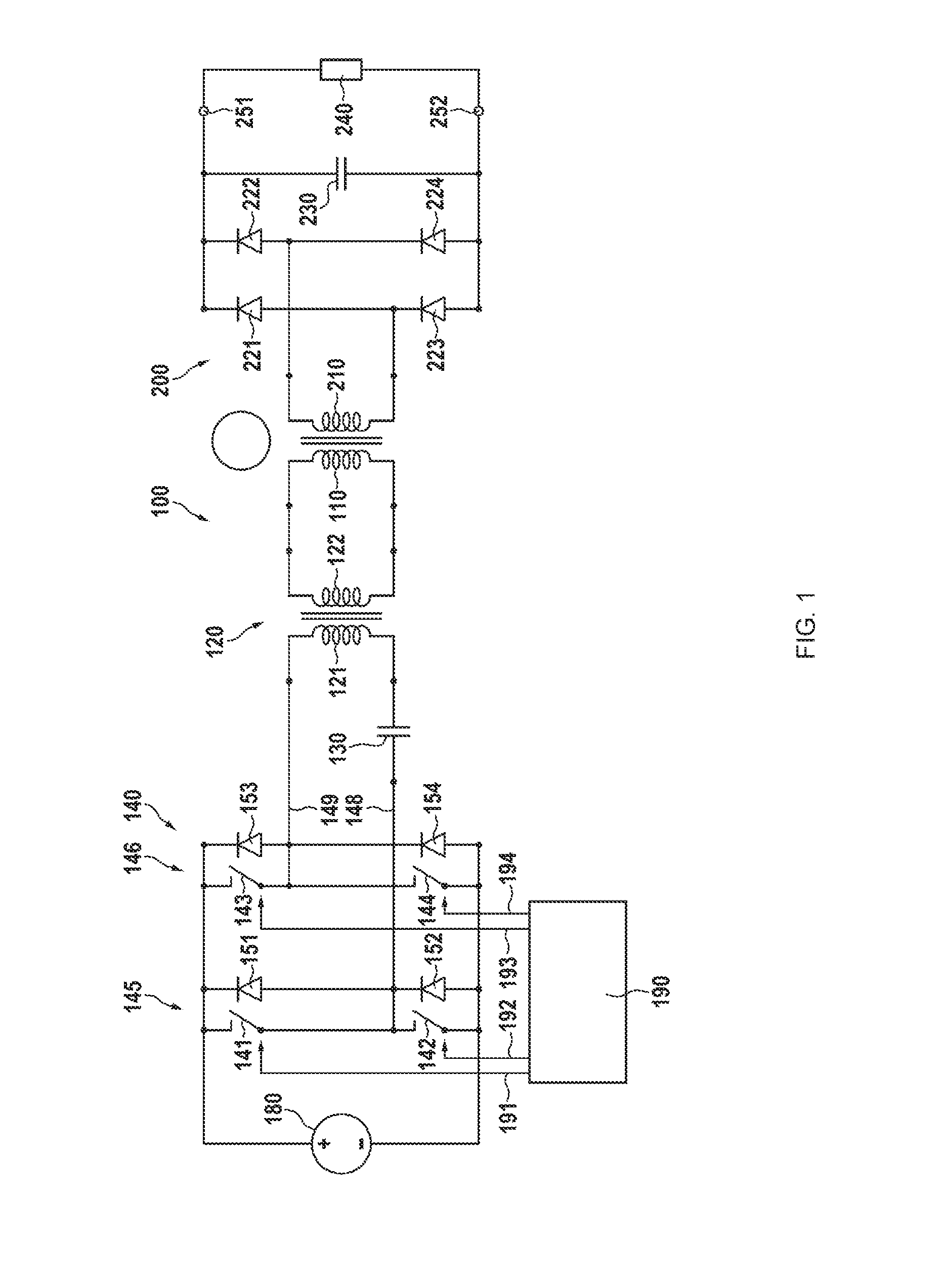
[0032]In FIG. 1, the circuit diagram of a preferred embodiment is shown. An inductively coupled contactless rotary joint has a primary side 100 and a secondary side 200. Preferably, the primary side 100 is the stationary side, whereas the secondary side 200 is the rotating side. It is obvious that stationary and rotating sides may be exchanged for coupling power from the rotating to the stationary side. At the primary side, there is a DC power source 180 having a positive output and a negative output for delivering DC power to an inverter 140, which generates an AC signal which is further coupled via a resonance capacitor 130, an optional transformer 120 having a primary winding 121 and a secondary winding 122 to a primary winding 110 of the rotating transformer.

[0033]The DC power source 180 may be a battery, a DC line, a rectifier circuit like a bridge or a one-way rectifier for rectifying an AC power line signal or a power factor correction circuit for generating a DC signal from ...


PUM


Abstract

An inductive power transfer circuit or inductive rotary joint has an inductive rotating coupler with a primary side and a primary winding rotatably arranged against a secondary side and a secondary winding. The secondary side is connected via a rectifier to a load. The stray inductance of the coupler together with a resonance capacitor a series resonance circuit having a series resonance frequency. An inverter in a full bridge circuit is provided for converting a DC input voltage into an AC voltage. The inverter is operable in a full bridge mode to deliver a high power level and in a half bridge mode to deliver a low power level. This results in a broad dynamic range, soft power on and improved safety, as switching between the modes may be controlled by a simple hardware.

Description

CROSS-REFERENCE TO RELATED APPLICATIONS[0001]This application claims priority from and benefit of the European Application No. 14198921.0 filed on Dec. 18, 2014. The disclosure of this European Application is incorporated by reference herein.BACKGROUND[0002]1. Field of the Invention[0003]The invention relates to an inductive power coupling device for coupling electrical power between two units that are rotatable against each other, specifically for power couplers used in computer tomography scanners. Such power couplers are also known as rotary joints.[0004]2. Description of Relevant Art[0005]In computer tomography (CT) scanners and other related machines high-power in the range from 10 kW up to more than 100 kW is transferred from a stationary side to a rotating side. There, a high voltage in the range of above hundred kilovolts is generated to produce x-ray radiation.[0006]In U.S. Pat. No. 7,054,411 a multiple channel inductive rotary joint is disclosed. It has inductive channels ...

Claims


Application Information

Patent Timeline
IPC IPC(8): H02J50/10H02M1/00
CPCH02J50/10H02J5/005H02M7/48H01F38/18H02M3/3378H05G1/10H02J50/12Y02B70/10H02M1/0058H02J2310/23A61B6/03H02M3/335
Inventor KRUMME, NILSHERRMANN, ULRICH
Owner SCHLEIFRING GMBH
Why Eureka
Try Eureka