
Methods and apparatuses for skin treatment using non-thermal tissue ablation

Active Publication Date: 2016-07-07
CYTRELLIS BIOSYST
View PDF2 Cites 63 Cited by
  • Summary
  • Abstract
  • Description
  • Claims
  • Application Information

AI Technical Summary

Benefits of technology

The patent describes devices, methods, and apparatuses for treating uneven surfaces, such as the face. These devices can conform to the skin surface even if it is uneven, and can also help to quickly heal compared to traditional surgery. The patent also implies that by treating a disease or condition in a person before it symptoms appear, the frequency or severity of the disease can be reduced. This is called "prophylactic treatment".

Problems solved by technology

Many human health issues arise from the damage or loss of tissue due to disease, advanced age, and / or injury.
Conventional surgical therapies (e.g., a face lift, brow lift, or breast lift) can be effective but are often invasive, inconvenient, and expensive, while scarring limits the applicability of surgery to certain treatment sites.
Although minimally invasive methods are available, such methods are generally less effective than surgical methods.
Methods using energy sources (e.g., laser, non-coherent light, radiofrequency, or ultrasound) can be effective at improving the architecture and the texture of the skin but are much less effective at tightening the skin or reducing skin laxity.
Neurotoxins, such as botulinum toxin, reduce the formation of dynamic wrinkles by paralysis of the injected muscles, but such toxins have minimal or no direct effect on skin tightness or laxity.
Finally, dermal fillers, such as hyaluronic acid, are injected in the dermal layer to smooth out wrinkles and improve contours, but such fillers do not directly tighten or reduce laxity of the skin.

Method used


Image

  • Methods and apparatuses for skin treatment using non-thermal tissue ablation
  • Methods and apparatuses for skin treatment using non-thermal tissue ablation
  • Methods and apparatuses for skin treatment using non-thermal tissue ablation

Examples


example 1

Drill Apparatus for Forming an Ablated Tissue Portion

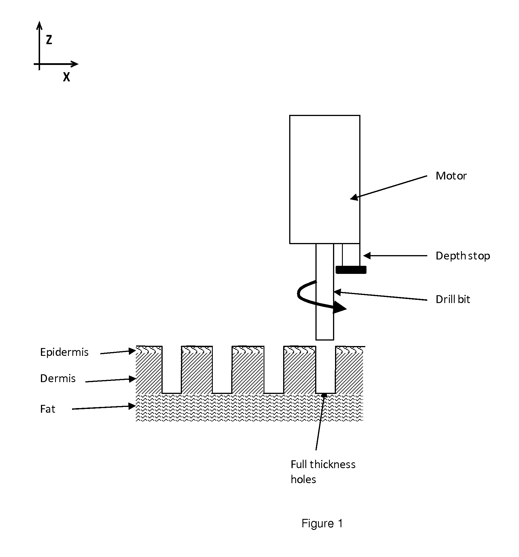
[0249]An ablated tissue portion for the treatment of skin can be formed by mechanical means. For example, a drill equipped with a depth stop, a drill bit configured to remove tissue and having a diameter less than 1 mm, can be used to form an ablated tissue portion (FIG. 1). The drill is positioned over the skin region to be ablated. The drill bit is rotated using the drill motor to a rotational speed sufficient for the drill bit to incise the tissue (e.g., a drill rotational speed between about 50 to 2500 rpm, such as about 500 rpm or any ranges described herein). As the drill bit enters the tissue, the device is moved in the Z direction until the depth stop makes contact with the skin surface. The drill bit rotation can be reversed to remove the drill bit and complete the ablation to form an ablated tissue portion.

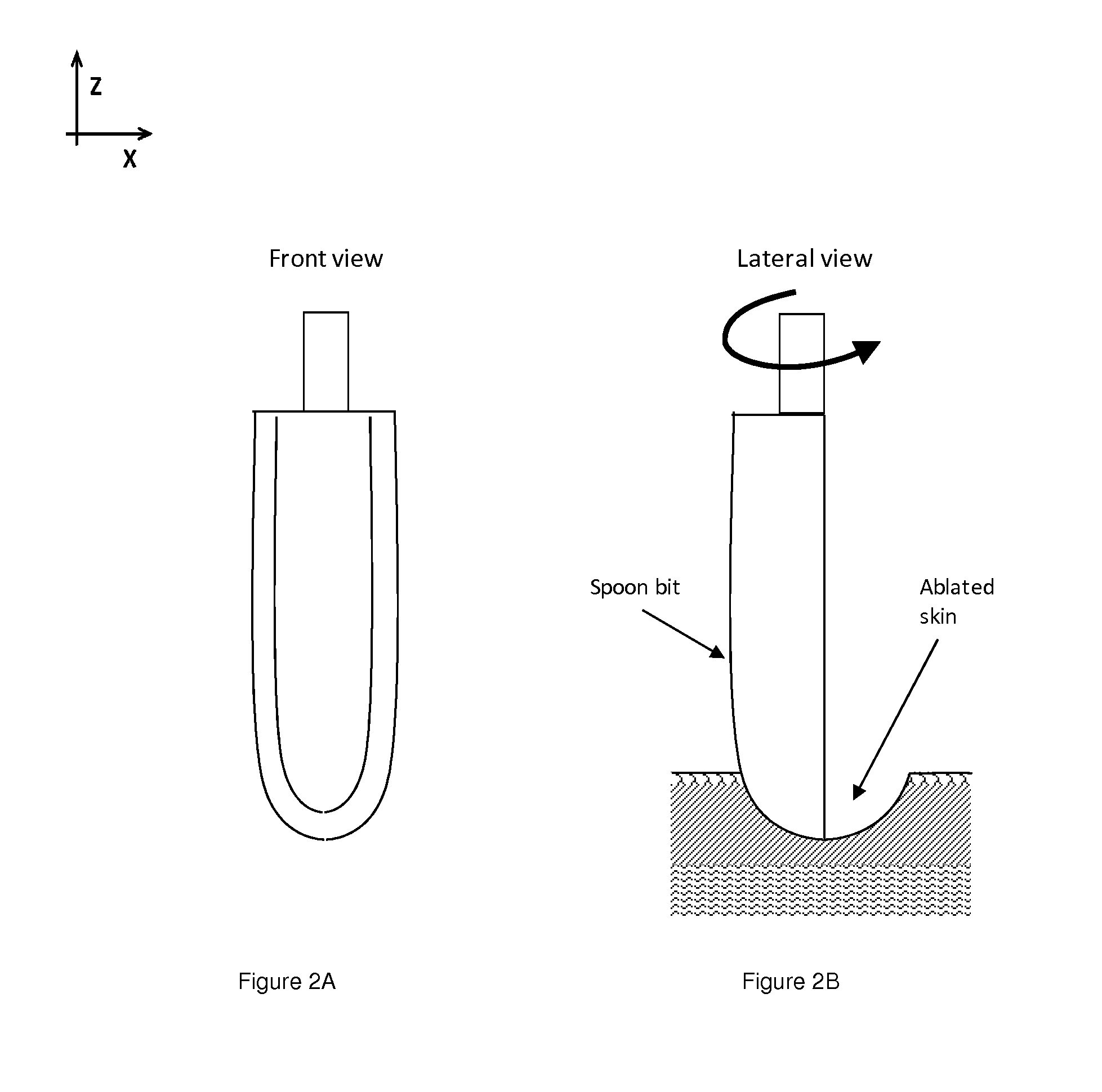
[0250]Many drill bit designs and materials can be used in the exemplary device and method. For example, a twist bit ...

example 2

Wire or Fiber Apparatus for Forming an Ablated Tissue Portion

[0251]The mechanical means for non-thermal ablation of tissue to form an ablated tissue portion can be a wire or a fiber attached to a rotating component. For example, a wire can be attached to a needle such that the wire creates an arc extending from the longitudinal axis of the needle (FIG. 3A). The wire can be attached to the needle adjacent to the needle tip and attached in a second location along the needle towards the proximal end of the needle (end attached to rotating component). In this configuration, the tip of the needle anchors itself into the tissue for ablation. The rotating component is activated and the wire rotates with the needle, sweeping out a volume of tissue as the wire turns. The rotational speed can be set to achieve the desired effect (e.g., slower rotation results in less aggressive ablation of tissue and faster rotation results in more aggressive ablation of tissue). The shape of the hole is dict...

example 3

Blade Apparatus for Forming an Ablated Tissue Portion

[0254]The mechanical means for ablation may include one or more blades. For example, an ablation apparatus can be formed by a square shaped tube having blades along the bottom edge of each wall of the square tube. In a further example, an array of square shaped tubes with blade edges (FIG. 4, an array of six square blades) having one or more square tubes separated by a distance configured to extract about 5-40% of the tissue area covered by the array (e.g., the sum of the area of all the square tubes is 5-40% of the total area covered by the array). The blades are pushed into the skin in the direction indicated by the arrow. Different hole patterns may be cut depending on the geometry and number of blades (e.g., a triangle, hexagon, or octagon). Blades may be inserted into the tissues with sufficient force and speed to produce a desired effect. The hole depth can be controlled by the depth of the blade or a stop feature on the app...


PUM


Abstract

Disclosed herein are methods, apparatuses, and devices for treating skin, such as skin tightening or for treating diseases, disorders, and conditions that would benefit from tissue area or volume reduction, skin restoration, skin tightening, skin lifting, or skin repositioning. Such methods and devices include an ablative apparatus, a removal apparatus, and / or a positioning apparatus.

Description

BACKGROUND OF THE INVENTION[0001]This invention relates to methods, apparatuses, and devices for treating skin and proximal tissue layers (e.g., such as fat, muscle, and facial SMAS (superficial muscular aponeurotic system)), such as skin tightening, or for treating diseases, disorders, and conditions that would benefit from tissue area or volume reduction, skin restoration, skin tightening, skin lifting, or skin repositioning, or tattoo removal.[0002]Many human health issues arise from the damage or loss of tissue due to disease, advanced age, and / or injury. In aesthetic medicine, elimination of excess tissue and / or skin laxity is an important concern that affects more than 25% of the U.S. population. Conventional surgical therapies (e.g., a face lift, brow lift, or breast lift) can be effective but are often invasive, inconvenient, and expensive, while scarring limits the applicability of surgery to certain treatment sites.[0003]Although minimally invasive methods are available, s...

Claims


Application Information

Patent Timeline
IPC IPC(8): A61B17/3209A61B17/3203A61B17/3205A61B17/34A61B18/02A61B18/20A61B17/14A61B17/32A61B18/14
CPCA61B17/3203A61B2017/00039A61B18/14A61B18/02A61B18/20A61B17/14A61B17/34A61B2018/143A61B2018/0293A61B2018/0262A61B2018/2005A61B2017/00765A61B2018/0047A61B2018/0016A61B2018/00577A61B17/32093A61B17/320068A61B2017/146A61B2017/00084A61B17/32053A61B18/203A61B2017/00747A61B2018/00613A61B2017/00756A61B2017/00769A61B17/147A61B2017/320082A61B2017/320069A61B2017/32007A61B2017/00761
Inventor GINGGEN, ALECLEVINSON, DOUGLASSTONE, DAVID
Owner CYTRELLIS BIOSYST
Learn More