Motor control device and motor control method

a technology of motor control device and control method, which is applied in the direction of motor/generator/converter stopper, electronic commutator, dynamo-electric converter control, etc., can solve the problems of control device performing unbalanced-drive switching for an entire time period

Active Publication Date: 2016-07-07
DENSO CORP
View PDF4 Cites 9 Cited by
  • Summary
  • Abstract
  • Description
  • Claims
  • Application Information

AI Technical Summary

Benefits of technology

[0007]It is an object of the present disclosure to provide a motor control device and a motor control method in which the rotatio

Problems solved by technology

When the magnitude of the ripple current exceeds the threshold value, the control device performs unbalanced-drive switching that the first output terminal is repeatedly and alternately connected to the high voltage side and the low voltag

Method used


Image

  • Motor control device and motor control method
  • Motor control device and motor control method
  • Motor control device and motor control method

Examples


first embodiment

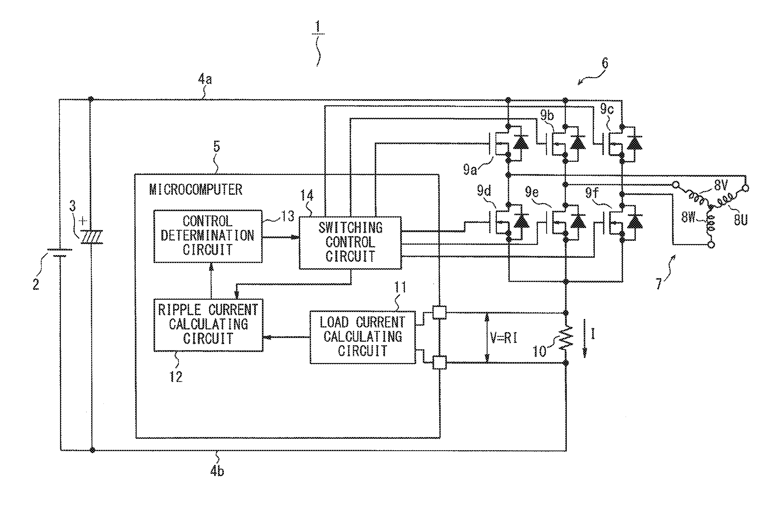
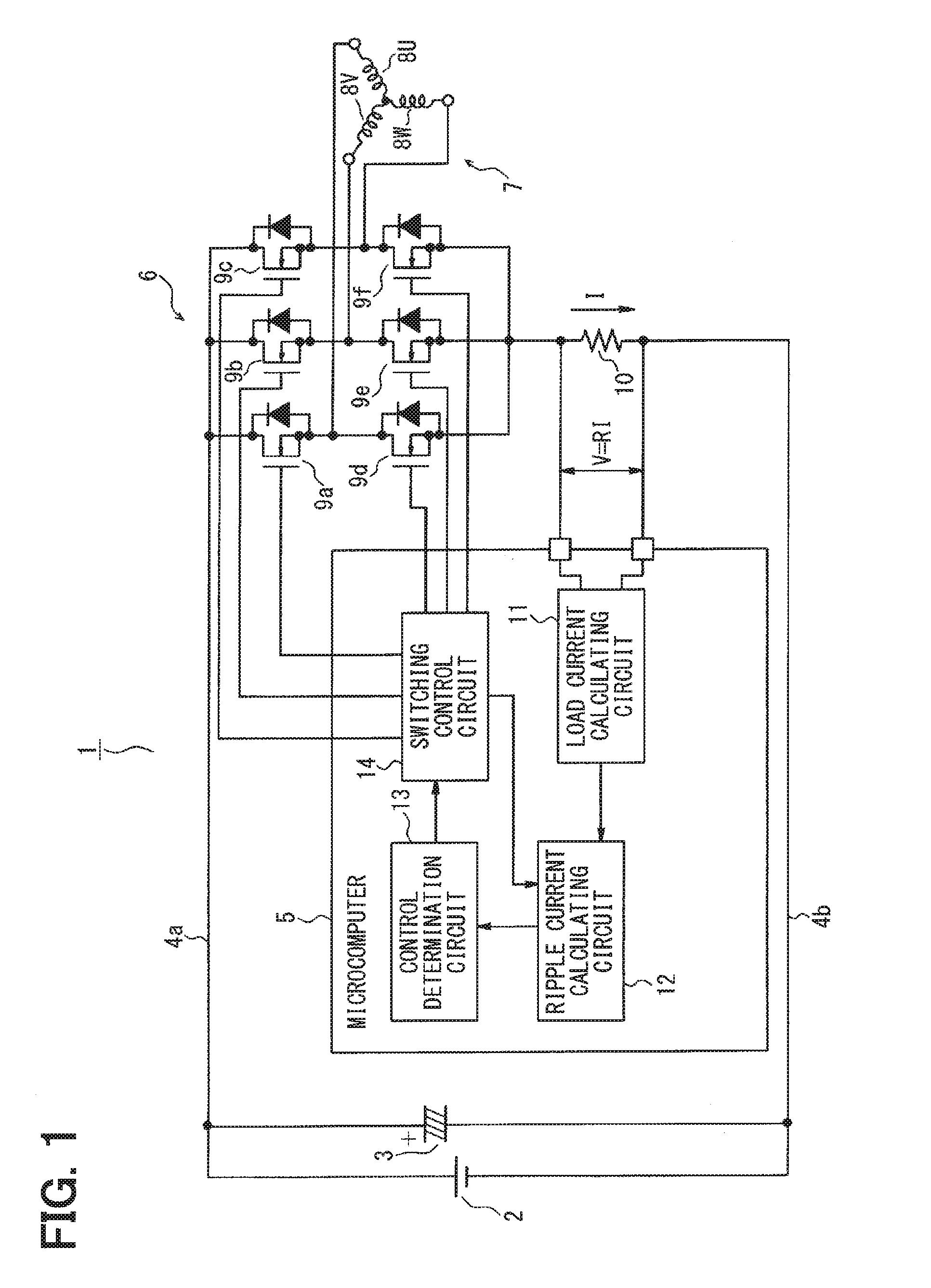
[0029]As illustrated in FIG. 1, an inverter device 1 is configured to be connected to a parallel circuit of a DC power supply (drive power supply) 2 and a smoothing capacitor (electrolytic capacitor) 3 via power supply lines (drive power supply lines) 4a and 4b. The inverter device 1 is configured to include a microcomputer (control device) 5 and an inverter circuit 6. Stator windings 8U, 8V, and 8W of a brushless DC motor 7 (hereinafter, simply referred to as a motor) are respectively connected to a U phase output terminal, a V phase output terminal, and a W phase output terminal of the inverter circuit 6. The respective one ends of the stator windings 8U, 8V, and 8W are connected together (star connection). For example, the motor 7 is an air-blowing fan motor mounted in a vehicle.

[0030]The inverter circuit 6 is configured such that six N-channel MOSFETs (switching devices) 9a to 9f are connected to each other in a three-phase bridge configuration. A freewheel diode (parasitic diod...

second embodiment

[0046]Hereinafter, the same reference signs will be assigned to the same portions as in the first embodiment. The same portions will not be described, and different portions will be described. As illustrated in FIG. 8, in an inverter device 21 in a second embodiment, a diode circuit (temperature detection device and ripple current estimating device) 22, in which multiple diodes are connected in series to each other, is disposed in the vicinity of a smoothing capacitor 3 so as to detect the temperature of the smoothing capacitor 3. The diode circuit 22 is connected in series to a current source 23, which is disposed on an anode side of the diode circuit 22, between the power supply and the ground.

[0047]A microcomputer 24 replacing the microcomputer 5 includes a diode temperature calculating circuit (temperature estimating device and ripple current estimating device) 25. The diode temperature calculating circuit 25 reads the terminal voltage of the diode circuit 22, that is, a voltage...

third embodiment

[0052]Hereinafter, the points of difference of a third embodiment with reference to the second embodiment will be described. As illustrated in FIG. 10, in an inverter device 31 in the third embodiment, a thermistor (temperature detection device and ripple current estimating device) 32 is disposed in the vicinity of a smoothing capacitor 3 so as to detect the temperature of the smoothing capacitor 3. The thermistor 32 is connected in series to a resistance element 33 between the power supply and the ground.

[0053]A microcomputer 34 replacing the microcomputer 5 includes a thermistor temperature detecting circuit (temperature estimating device and ripple current estimating device) 35 replacing the diode temperature calculating circuit 25. The thermistor temperature calculating circuit 35 reads a terminal voltage Vt of the thermistor 32, and performs A / D conversion on the terminal voltage Vt. The thermistor temperature calculating circuit 35 obtains the internal temperature of the smoot...


PUM


Abstract

A motor control device for controlling a brushless DC motor in a PWM control manner using an inverter circuit according to a position-sensorless method includes: a ripple current estimating device; and a control device. When the magnitude of the ripple current is less than or equal to a threshold value, the control device performs balanced-drive switching that a first output terminal of the inverter circuit is repeatedly and alternately connected to high and low voltage sides of a drive power supply, and the second output terminal of the inverter circuit is repeatedly and alternately connected to the low and high voltage sides. When the magnitude of the ripple current exceeds the threshold value, the control device performs unbalanced-drive switching that the first output terminal is repeatedly and alternately connected to the high and low voltage sides, and the second output terminal is connected only to the low voltage side.

Description

CROSS REFERENCE TO RELATED APPLICATION[0001]This application is based on Japanese Patent Application No. 2013-254968 filed on Dec. 10, 2013, the disclosure of which is incorporated herein by reference.TECHNICAL FIELD[0002]The present disclosure relates to a motor control device and a motor control method which controls a brushless DC motor in a PWM manner via an inverter circuit according to a position-sensorless method.BACKGROUND ART[0003]It is deemed that the period of ringing caused by switching becomes longer than the pulse width of a PWM signal in a control region in which the duty ratio of the PWM signal is decreased when a brushless DC motor is controlled in a pulse width modulation (PWM) manner, and driven according to a position-sensorless method. In this case, the rotational angle of a rotor cannot be accurately detected, which is a problem.[0004]Patent Literature 1 discloses technology (referred to as “balanced-drive switching”) by which switching devices positioned on up...

Claims


Application Information

Patent Timeline
IPC IPC(8): H02P6/10H02P27/08H02P6/18H02P6/06H02P6/08H02P6/182
CPCH02P6/10H02P27/08H02P6/18H02P6/182H02P29/68
Inventor NISHIYAMA, YASUHARU
Owner DENSO CORP
Why Eureka
Try Eureka