Rare earth permanent magnet and method for manufacturing thereof

Active Publication Date: 2016-07-14
HYUNDAI MOTOR CO LTD
View PDF8 Cites 8 Cited by
  • Summary
  • Abstract
  • Description
  • Claims
  • Application Information

AI Technical Summary

Benefits of technology

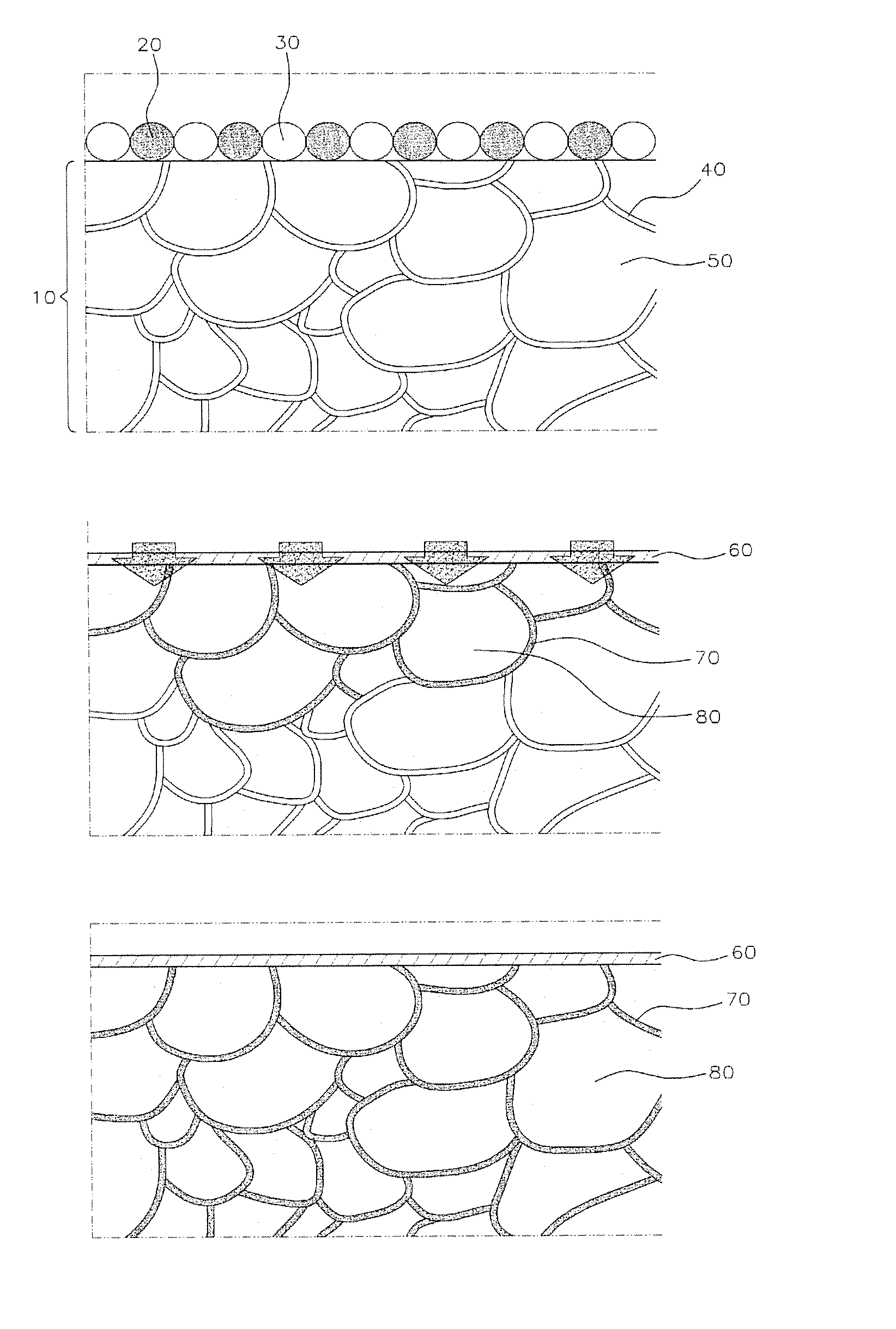
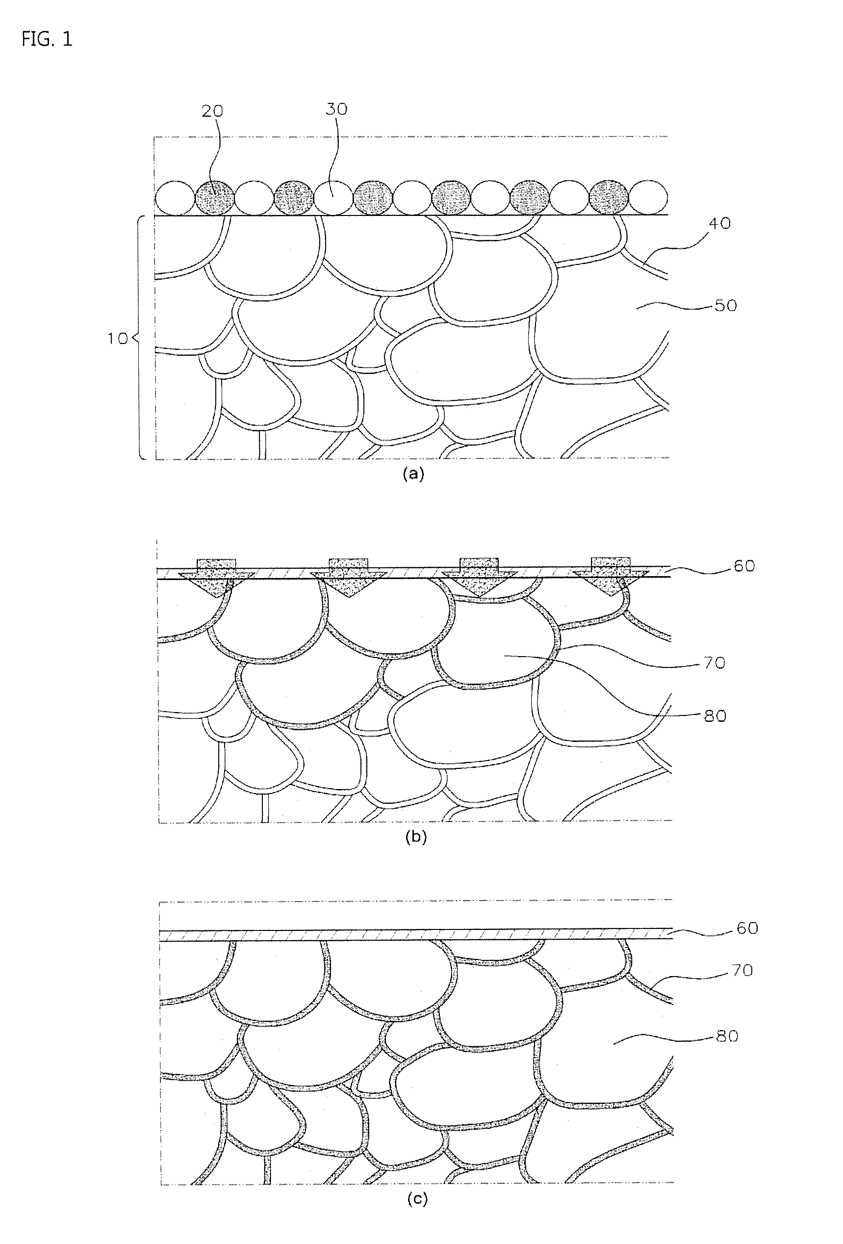
[0020]One aspect of the present disclosure provides a grain boundary diffusion method, which inhibits residual magnetic flux density of a sintered magnet body and effectively improves coercive force, and a rare earth permanent magnet manufactured thereby.
[0021]Further, another aspect of the present disclosure pro

Problems solved by technology

But rare earth elements such as Dy and Tb are very expensive, and therefore, cause the total price of the permanent magnet to increase, and reduce the price competitiveness of the motor.
However, this method has a problem in that the element of the alloy powder may diffuse into the particle when sintering.
However, in the grain boundary diffusion method, there are many problems when using the evaporation or the sputtering method for mass production, and this may lead to decreased productivity.
However, there is a disadvantage in that the rare earth element diffuses by a substitution reaction between the powder and the magnet ingredients, so it is difficult to introduce them into the magnet in a large quantity.
This is an excellent method in terms of introducing the rare earth element on a large scale, but it has disadvantages in that handling of the calcium or calcium hydride powder is not easy and productivity may be lowered.
Regarding the grain boundary diffusion methods, one technique attaches the rare earth element to the NdFeB sintered magnet surface in order to prevent a reduction of coercive force, which is reduced when the NdFeB sintered magnet surface is processed for the purpose of thinning and the like, but there is a problem in that the coercive force improvement effect

Method used


Image

  • Rare earth permanent magnet and method for manufacturing thereof
  • Rare earth permanent magnet and method for manufacturing thereof

Examples


Example

[0038]It should be understood that the appended drawings are not necessarily to scale, presenting a somewhat simplified representation of various preferred features illustrative of the basic principles of the inventive concept. The specific design features of the present invention as disclosed herein, including, for example, specific dimensions, orientations, locations, and shapes will be determined in part by the particular intended application and use environment.

[0039]In the figures, reference numbers refer to the same or equivalent parts of the present inventive concept throughout the several figures of the drawing.

DETAILED DESCRIPTION

[0040]Hereinafter reference will now be made in detail to various embodiments of the present inventive concept, examples of which are illustrated in the accompanying drawings and described below. While the inventive concept will be described in conjunction with exemplary embodiments, it will be understood that present description is not intended to...


PUM

PropertyMeasurementUnit
Temperatureaaaaaaaaaa

Abstract

A method for manufacturing a rare earth permanent magnet includes manufacturing an NdFeB sintered magnet. A grain boundary diffusion material in the form of a mixed powder comprising an alloy powder containing Re1aMb or M; and Re2 oxide or Re2 fluoride is disposed on a surface of the NdFeB sintered magnet. The grain boundary diffusion material is heated to diffuse at least one of Re1, Re2 and M into a grain boundary part inside the sintered magnet or a grain boundary part region of a sintered magnet main phase grain. Re1 and Re2 are each rare earth elements selected from the group consisting of dysprosium, terbium, neodymium, praseodymium, and holmium, M is a metal compound consisting of copper, zinc, tin, and aluminum, 0.1<a<99.9, and a+b=100.

Description

CROSS-REFERENCE TO RELATED APPLICATION[0001]This application claims under 35 U.S.C. §119(a) the benefit of priority to Korean Patent Application No. 10-2015-3336, filed on Jan. 9, 2015, the entire content of which is incorporated herein by reference.TECHNICAL FIELD[0002]The present disclosure relates to a rare earth permanent magnet, wherein coercive force is increased while reduction of residual magnetic flux density of a sintered magnet body is inhibited by using a heat treatment for grain boundary diffusion to the inside of the sintered magnet body and at a main phase grain of the sintered magnet body, which is manufactured by mixing metal alloy powder and a rare earth compound and then coating thereof, and a method for manufacturing thereof.BACKGROUND[0003]In recent years, an NdFeB (Nd—Fe—B based) permanent magnet having excellent magnetic characteristics has been developed that enables high power and size reduction of a motor, and the scope of its use for various electronic app...

Claims


Application Information

Patent Timeline
IPC IPC(8): H01F1/057H01F41/02B22F5/00B22F3/10B22F3/26
CPCH01F1/0577B22F3/10B22F2003/248B22F5/00H01F41/0293B22F3/26B22F2998/10B22F2999/00C22C38/002C22C38/005C22C38/06C22C38/10C22C38/16C22C2202/02B22F3/02B22F2202/05B22F2201/10B22F2003/241B22F2201/02B22F2201/11B22F2201/20H01F1/06H01F41/0246H01F41/0253
Inventor LEE, JAE-RYUNGPARK, KUN-MINLEE, HYUNG-JUJUNG, YEON-JUN
Owner HYUNDAI MOTOR CO LTD
Why Eureka
Try Eureka