Control device for a hybrid vehicle

a control device and hybrid technology, applied in the direction of electric control, engine starters, machines/engines, etc., can solve the problems of increasing the risk of producing a state in which the brake pedal cannot be significantly depressed and the driver is imparted with a sense of unease, and achieve the effect of regenerative energy

Inactive Publication Date: 2016-08-11
NISSAN MOTOR CO LTD
View PDF0 Cites 8 Cited by
  • Summary
  • Abstract
  • Description
  • Claims
  • Application Information

AI Technical Summary

Benefits of technology

[0010]Specifically, keeping the engine rotation speed at or above a predetermined rotation speed ensures a negative pressure, and even if the driver repeats the brake pedal operation prior to the vehicle coming to a stop, a boosting device is able to deliver an assist function, making it possible for the brake pedal to be depressed. Accordingly, braking can be performed without imparting the driver with a sense of unease. In addition, since negative pressure can be obtained, the predetermined vehicle speed Vne

Problems solved by technology

When the braking operation is repeated in a state in which the engine is stopped, the negative pressure of the brake booster (boosting means or device) decr

Method used


Image

  • Control device for a hybrid vehicle
  • Control device for a hybrid vehicle
  • Control device for a hybrid vehicle

Examples


first embodiment

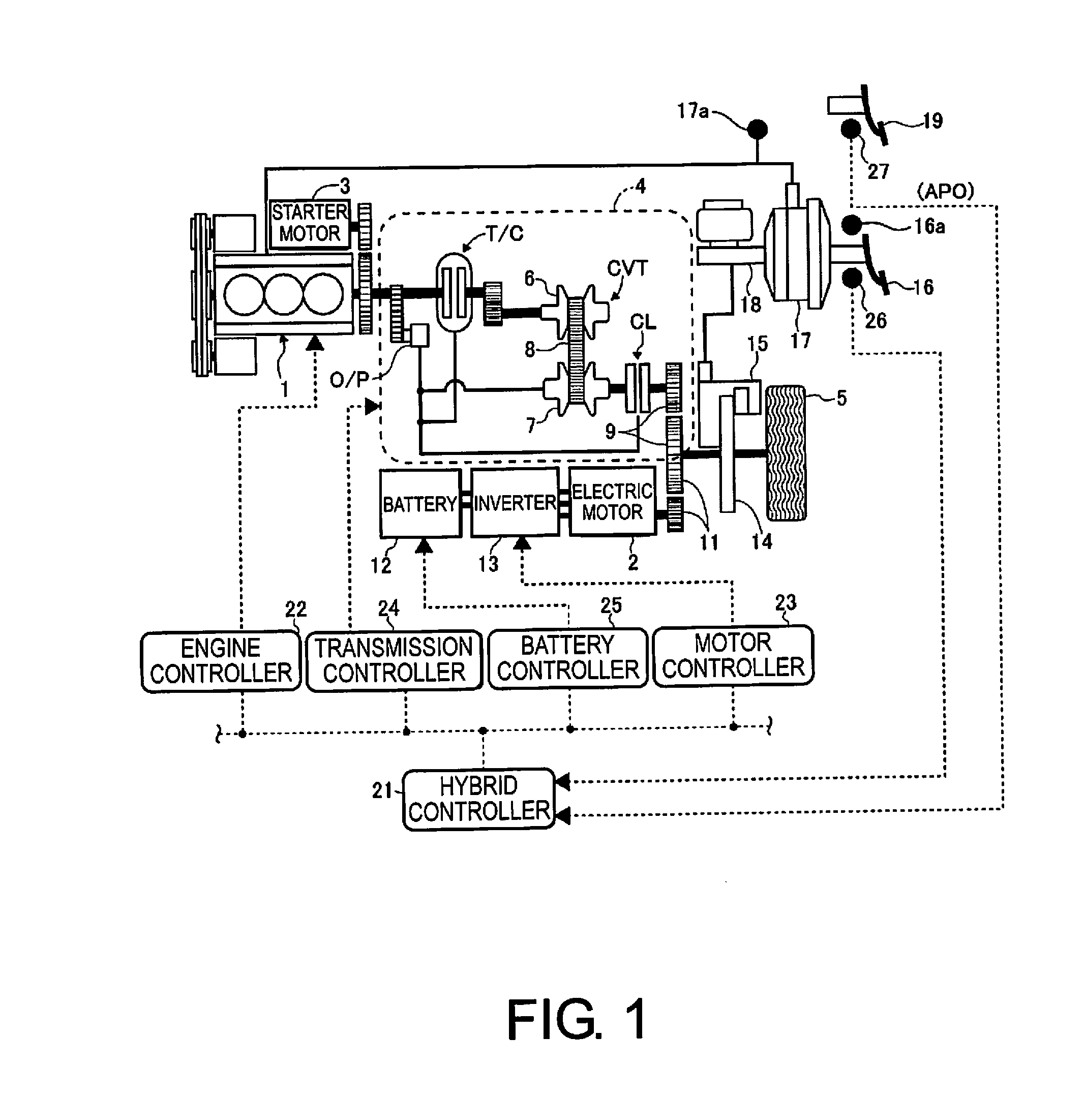
[0019]FIG. 1 is a schematic system diagram showing a driving system and an overall control system of a hybrid vehicle with a control device according to a first embodiment. The hybrid vehicle in FIG. 1 has an engine 1 and an electric motor 2 mounted thereon as drive sources, and the engine 1 is started by a starter motor 3. The engine 1 is drivingly coupled to a drive wheel 5 by a V-belt-type continuously variable transmission 4 so as to be capable of being decoupled as appropriate. An overview of the V-belt-type continuously variable transmission 4 will now be given below.

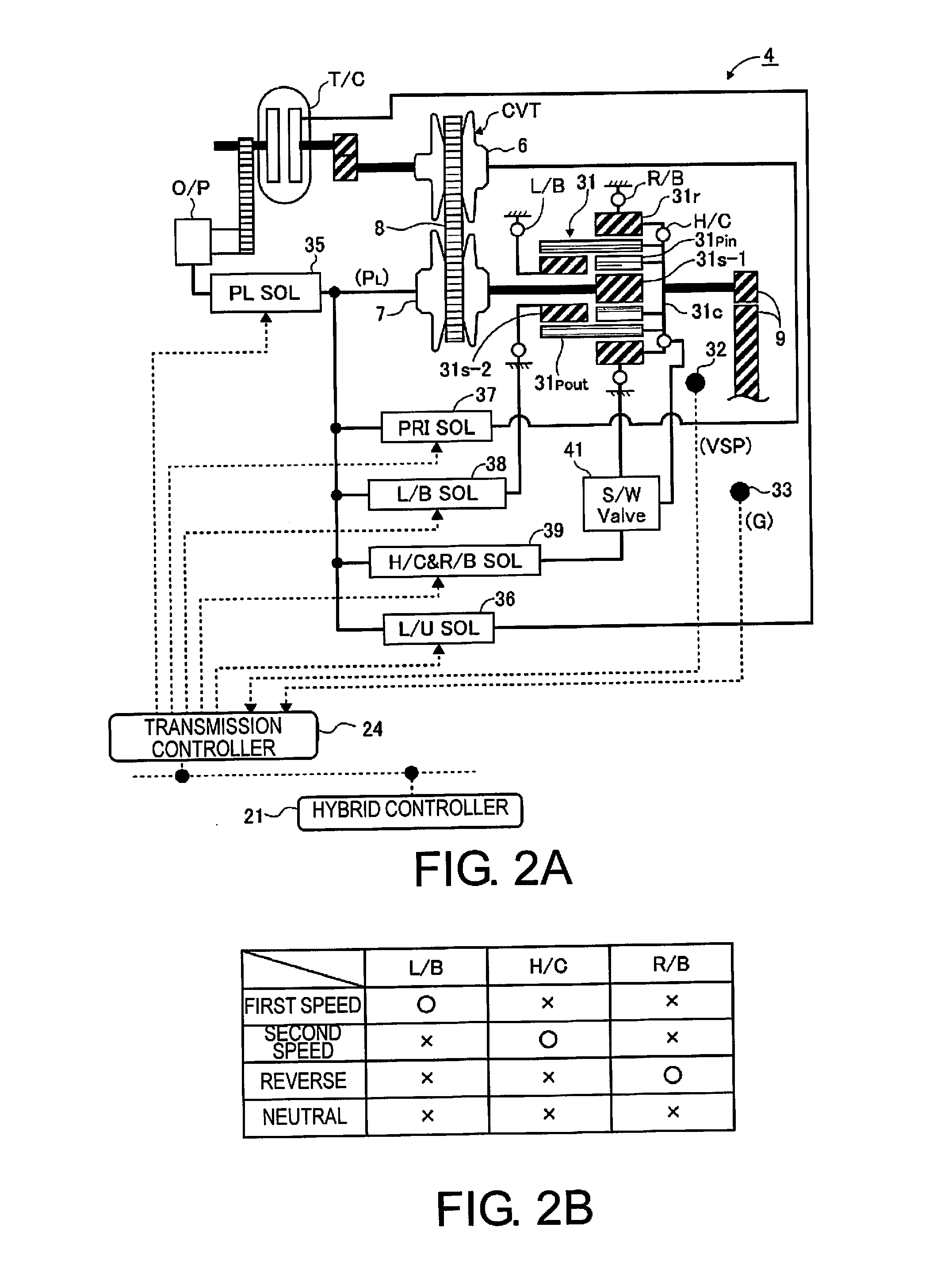
[0020]The V-belt-type continuously variable transmission 4 is a continuously variable transmission mechanism CVT comprising a primary pulley 6, a secondary pulley 7, and a V-belt 8 extended between the pulleys 6, 7. The primary pulley 6 is coupled to a crank shaft of the engine 1 via a torque converter T / C having a lock-up clutch. The secondary pulley 7 is coupled to the drive wheel 5 via a clutch CL and a final g...

second embodiment

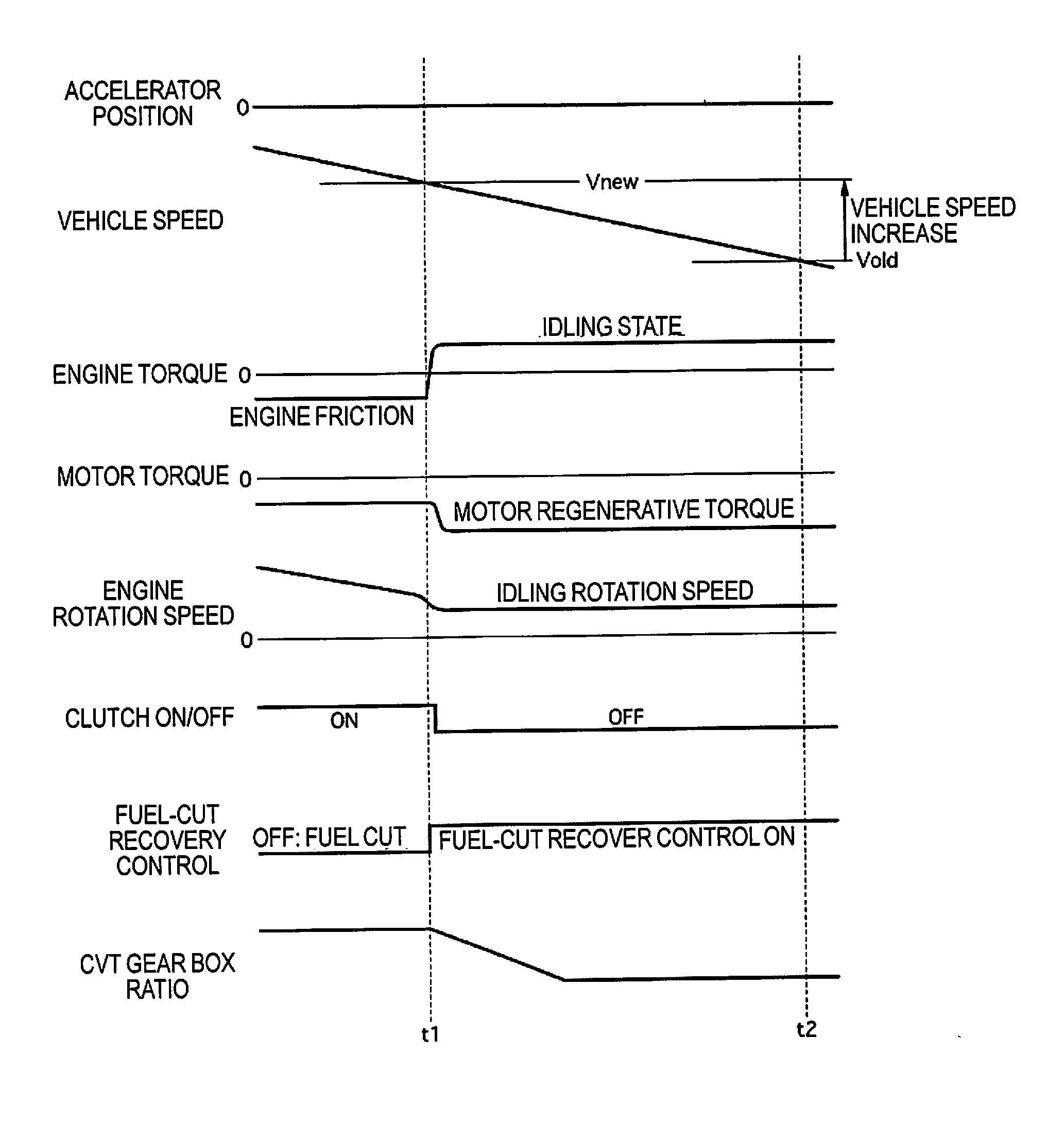
[0075]A second embodiment will now be described. The basic configuration is the same as that of the first embodiment; therefore, a description will be given with regards to the differences. In the first embodiment, when the EV deceleration regeneration mode is selected, the engine 1 is put in an idling state. In contrast, in the second embodiment, as a brake request made by the driver, the negative pressure of the negative pressure-type brake booster 17 is detected by the negative pressure sensor 17a, and the presence of a predetermined value (negative pressure necessary for braking) is determined. If the predetermined value is not available, a negative pressure request is outputted, and the operation state of the engine 1 is maintained. If the negative pressure is available, the negative pressure request is stopped, i.e., the fuel-cut recovery control is prohibited from taking place. The negative pressure necessary for braking refers to, e.g., a value at which a rapid deceleration ...

third embodiment

[0082]A third embodiment will now be described. The basic configuration is the same as that of the second embodiment; therefore, a description will be given with regards to the differences. In the third embodiment, when the operation of the engine 1 is stopped as with the second embodiment and the braking force requested by the driver subsequently becomes equal to or greater than a predetermined value, the clutch CL is engaged to ensure negative pressure is obtained. In the third embodiment, with regards to the required braking force value, a determination is made on the basis of whether or not the stroke amount detected by the stroke sensor 16a is equal to or greater than a predetermined value. However, the above is not provided by way of limitation; any configuration capable of detecting the brake request made by the driver, such as one for detecting, e.g., the master cylinder pressure or the depression force, is also possible.

[0083]FIG. 5 is a time chart showing the control proce...


PUM


Abstract

A control device in a hybrid vehicle includes a controller capable of switching, between an operating state and a non-operating state, a fuel-cut recovery control in which engine rotation speed is kept at or above a predetermined rotation speed by starting supply of fuel upon the engine rotation speed falling to the predetermined rotation speed from a state in which the engine rotation speed is higher than the predetermined rotation speed and the supply of fuel is stopped.

Description

CROSS-REFERENCE TO RELATED APPLICATIONS[0001]This application is a U.S. National stage application of International Application No. PCT / JP2013 / 079423, filed Oct. 30, 2013, which claims priority to JP Patent Application No. 2012-251776 filed on Nov. 16, 2012, the contents of each of which are hereby incorporated herein by reference.BACKGROUND[0002]1. Field of the Invention[0003]The present invention relates to a control device for a hybrid vehicle that has an engine and an electric motor mounted thereon as power sources, the device making it possible to select between an electric travel mode (EV mode), in which traveling is performed using the electric motor only, and a hybrid travel mode (HEV mode), in which traveling is performed using the electric motor and the engine.[0004]2. Background Information[0005]Conventionally known hybrid vehicles of such description include the type disclosed in Japanese Laid-Open Patent Application No. 2002-139136, in which an engine, which is one of t...

Claims


Application Information

Patent Timeline
IPC IPC(8): B60W20/14B60W10/02B60W10/06B60K6/387B60W10/18B60W20/30B60K6/543B60W10/107B60W10/08B60L50/16
CPCB60K6/48Y02T10/6221B60W10/02B60W10/06B60W20/00F02D41/126F02N11/0822F02D29/02F02N2200/102Y02T10/48B60W30/18127B60L11/14B60W2710/1005B60W2710/0644B60W2540/12B60W20/30B60W10/18Y10S903/947B60W10/08B60K6/387B60W20/14Y10S903/93B60Y2200/92B60W10/107B60K6/543B60W10/105B60W10/30B60W2710/021B60W2710/08B60W2710/10B60W2710/244B60L7/24B60L15/2009B60L15/2054B60L2240/423B60L2240/486B60L2240/507B60L50/16Y02T10/40Y02T10/62Y02T10/64Y02T10/7072Y02T10/72Y02T10/70
Inventor SHIGEMOTO, SHUNSUKENAGAMINE, MORIHIRO
Owner NISSAN MOTOR CO LTD
Why Eureka
Try Eureka