
Power amplification device and method

Active Publication Date: 2016-08-25
SAMSUNG ELECTRONICS CO LTD
View PDF1 Cites 24 Cited by
  • Summary
  • Abstract
  • Description
  • Claims
  • Application Information

AI Technical Summary

Benefits of technology

The patent describes a way to improve the performance of a reception device by offsetting the switching frequency, which reduces harmonics that may interfere with the reception. This also prevents degraded conduction caused by radiation noise or incomplete radiation shielding.

Problems solved by technology

When the multi-carrier transmission scheme and the multidimensional modulation scheme are transmitted through a High Power Amplifier (HPA), signal distortion may be caused by nonlinear characteristics which the HPA has.

Method used


Image

  • Power amplification device and method
  • Power amplification device and method
  • Power amplification device and method

Examples


Embodiment Construction

Technical Problem

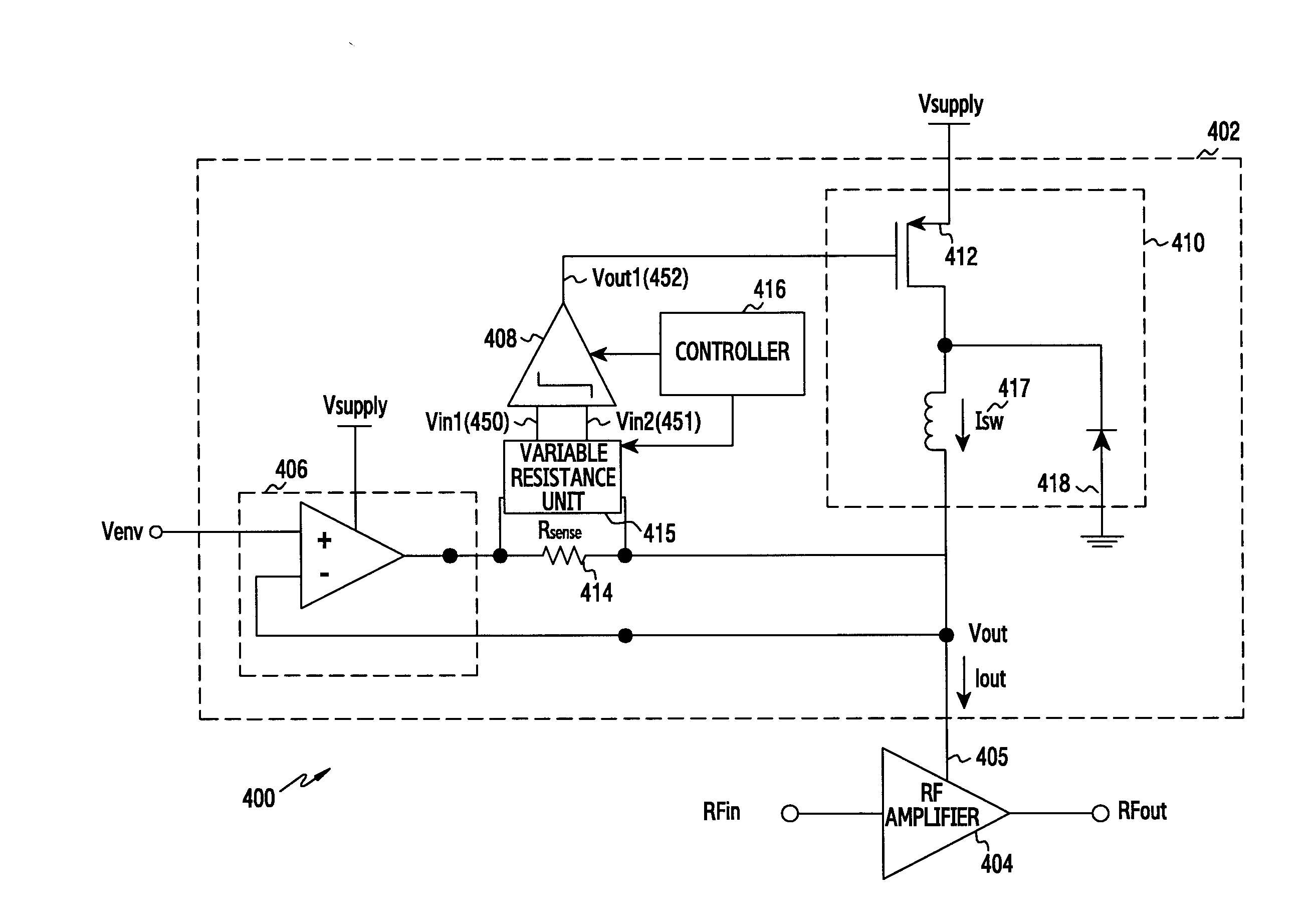
[0006]In the prior art, when a switching frequency of a DC-DC converter of an ET power amplifier or harmonics of the switching frequency are included in a reception band, reception conduction and a switching noise flows to a reception path by switching harmonics, thereby radiatively generating performance degradation.

[0007]Various embodiments of the present disclosure may provide a power amplification apparatus and method for applying an offset to the switching frequency to allow the switching harmonic frequency to escape from the reception band range when a DC-DC harmonic frequency is included in a reception band range due to the switching operation of a power modulator for controlling the bias voltage of the power amplifier.

[0008]Various embodiments of the present disclosure may provide a power amplification apparatus and method for improving a reception conduction performance by applying an offset to the switching frequency to allow the switching frequency and th...


PUM


Abstract

Various embodiments of the present invention relate to a power amplification device and method, wherein the power amplification device can comprise: a power amplifier; a switch mode converter for controlling a bias of the power amplifier; a comparator for providing a switching signal to the switch mode converter according to an envelope signal; and a control unit for determining whether a switching frequency of the switch mode converter is within a specific band and applying an offset to the switching frequency so as to deviate from the specific band if the switching frequency of the switch mode converter is within the specific band. Various other embodiments can be carried out.

Description

TECHNICAL FIELD[0001]The present disclosure relates to an apparatus and method for power amplification for reducing interference which affects a receiver by a transmitter power amplifier in a communication apparatus.BACKGROUND ART[0002]A wireless communication system has usually used a digital modulation scheme in order to efficiently use limited frequency resources. A digital modulated signal may be transferred to an antenna through an amplification process of a signal using a Radio Frequency (RF) power amplifier according to the purpose.[0003]Meanwhile, a multi-carrier transmission scheme and a multidimensional modulation scheme which can transmit a lot of information according to user requirements for high-speed and high-capacity data processing have been developed. When the multi-carrier transmission scheme and the multidimensional modulation scheme are transmitted through a High Power Amplifier (HPA), signal distortion may be caused by nonlinear characteristics which the HPA ha...

Claims


Application Information

Patent Timeline
IPC IPC(8): H03F1/02H03F3/24H03F3/193
CPCH03F1/0261H03K3/0377H03F3/195H03F3/245H03F3/45475H03F2200/555H03F2200/78H03F2203/45522H03F2203/45528H03F2203/45591H03F2203/45594H03F1/0216H03F2200/102H03F2200/451H03F2200/351H03F3/193H02M1/44H02M3/156H03F1/0227H03F1/32
Inventor YANG, DONG-IL
Owner SAMSUNG ELECTRONICS CO LTD
Learn More