Integrated devices and systems for free-space optical coupling

Active Publication Date: 2016-09-22
PACIFIC BIOSCIENCES
View PDF16 Cites 53 Cited by
  • Summary
  • Abstract
  • Description
  • Claims
  • Application Information

AI Technical Summary

Benefits of technology

[0024]In some embodiments, the system comprises an intervening optical element, such as an optical lens element, between the integrated optical delivery device and the integrated target waveguide device. In some of these embodiments, the integrated optical delivery device comprises a plurality of optical outputs, wherein at least one of the plurality of optical outputs has a numerical apert

Problems solved by technology

Such systems are frequently complex and costly and tend to have significant space requirements.
They are therefore not well suited for use in connection with an analytical system having a removable sample holder, where the optical output from an optical delivery device, such as a traditional optical train, is normally coupled to the target sample holder through free space.
In additi

Method used


Image

  • Integrated devices and systems for free-space optical coupling
  • Integrated devices and systems for free-space optical coupling
  • Integrated devices and systems for free-space optical coupling

Examples


example 1

Planar Lightwave Circuit with Tap Array at 532 nm

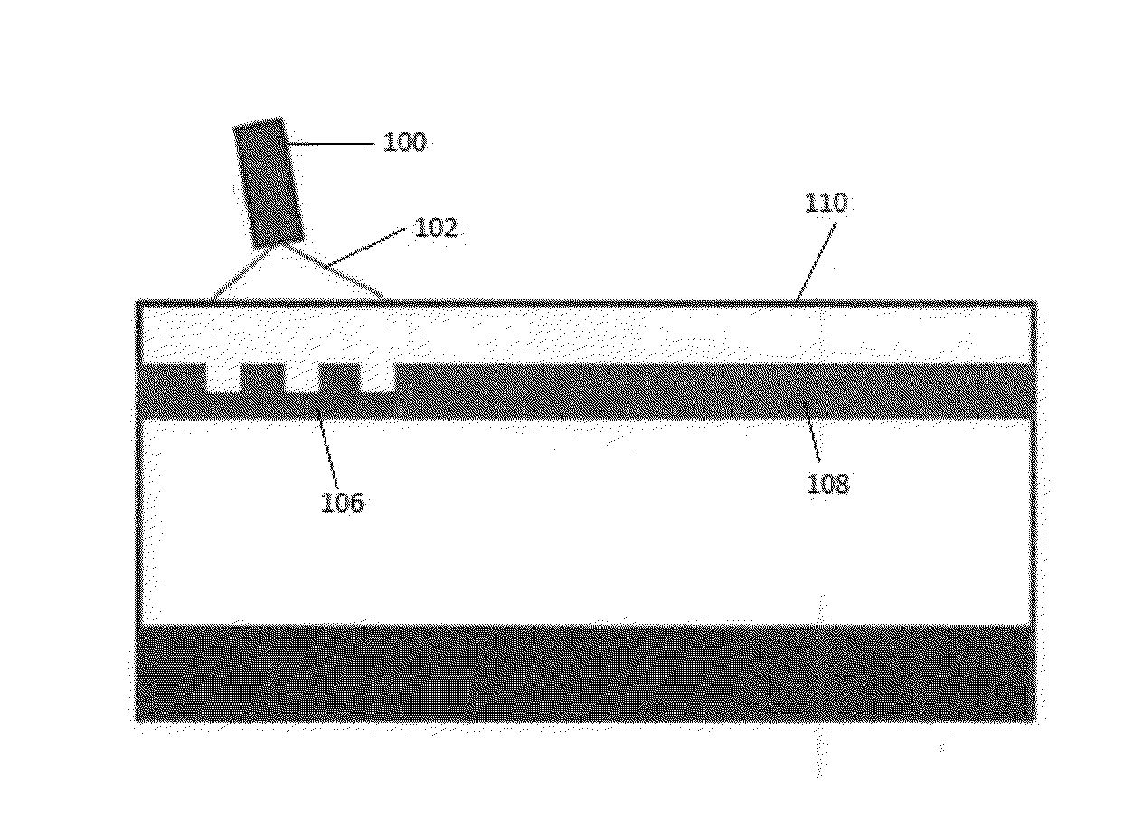
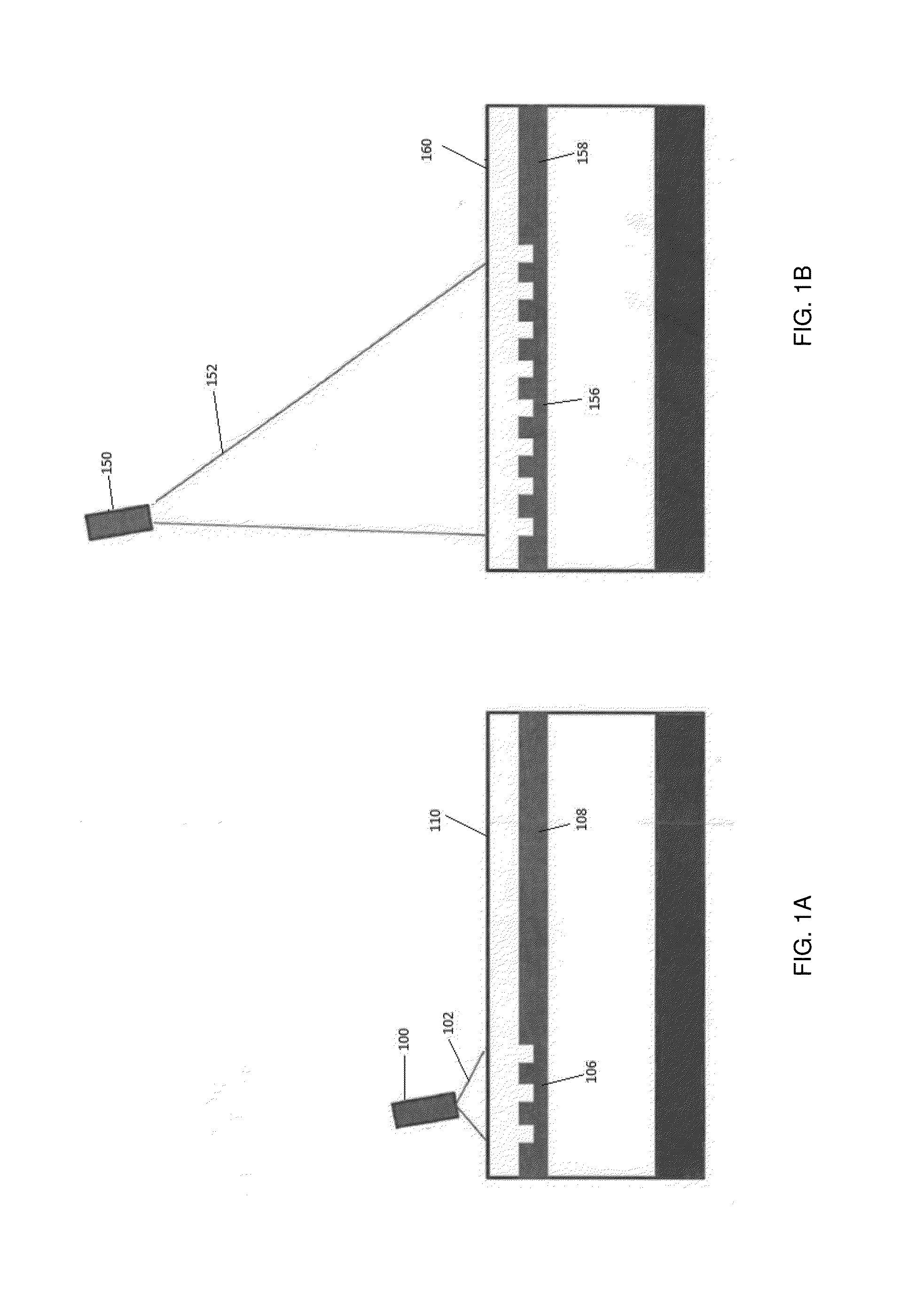
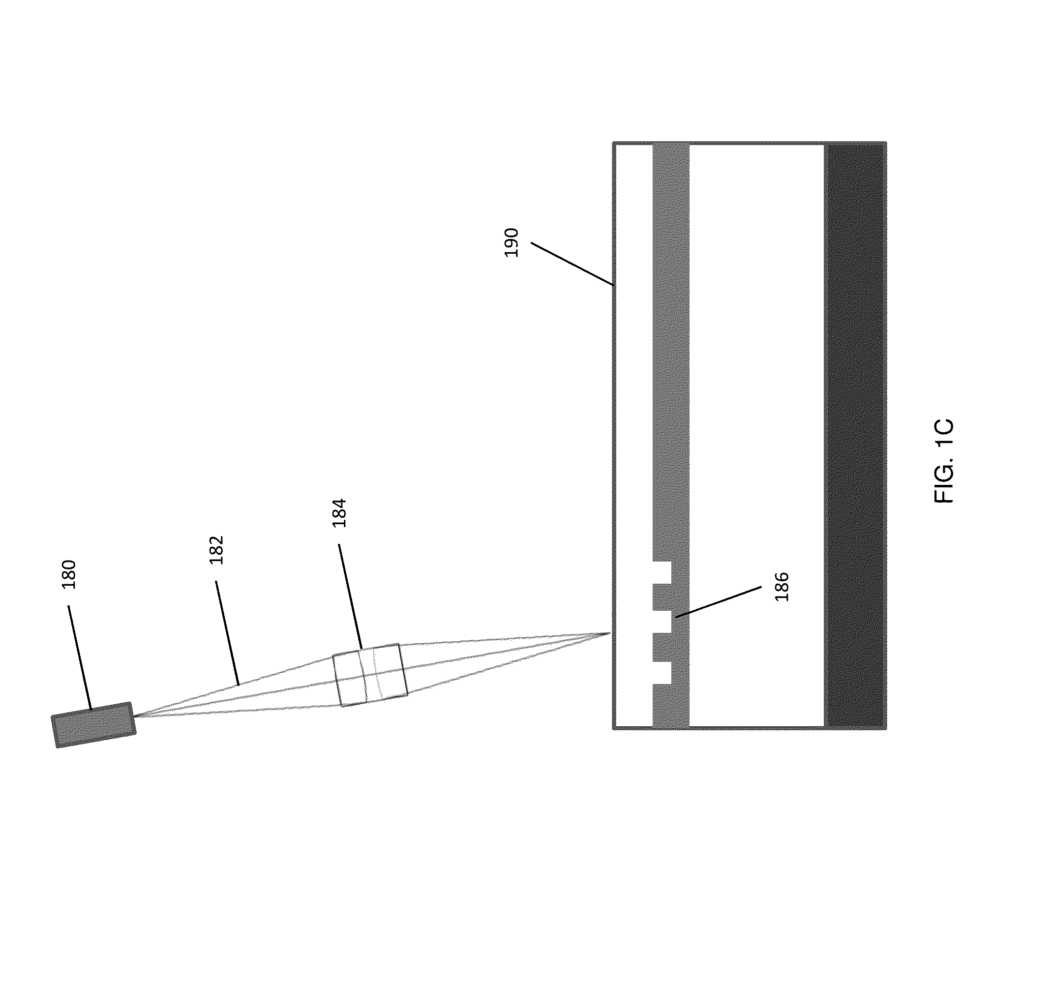
[0125]This example describes the design, optimization, and fabrication of a fibered chip, composed of a series of 11 single-mode waveguides to provide a PLC coupling function. An array of taps and photodiodes are also present on the PLC chip for laser-power-monitoring purposes. The modal behavior of the waveguide is optimized in the design process.

[0126]The PLC coupler prepared according to this example is an advanced optical component based on a combination of waveguides, taps, photodetectors, and polarization-maintaining fibers. The device is a passive waveguide chip that integrates eleven waveguides and concentrates the fiber cores into as small as possible an area. The process involves four main steps:

[0127]First, the waveguide process is optimized in order to create single-mode waveguides with a numerical aperture as close as possible to 0.072 and with a mode shape as round as possible.

[0128]Second, tap couplers are developed. Tw...

example 2

Planar Lightwave Circuit with Two Visible Wavelength Laser Inputs

[0154]This example provides an alternative PLC hardware coupler suitable for use in an integrated DNA sequencing system. The PLC coupler is designed to be included in a free space optical system. Specifically, the unit provides a source of structured illumination at 532 nm in a free space optical system for the sequencing product. The unit selectively splits and routes light from two input sources to eight main output sources, and two pairs of “outriggers” which are used for monitoring purposes. See FIG. 11.

[0155]Important features of the device include without limitation:[0156]Low insertion loss, and low back-reflection[0157]Maintenance of input PER[0158]Capable of high optical power[0159]Accurate symmetric and asymmetric power splits[0160]Accurate position of output waveguides[0161]Telecentric output[0162]Integration with high performance pigtails that are robust against typical handling, and a package that supports ...


PUM

PropertyMeasurementUnit
Poweraaaaaaaaaa
Distanceaaaaaaaaaa
Distanceaaaaaaaaaa

Abstract

Optical delivery devices and integrated analytical systems comprising the optical delivery devices are provided. The optical delivery devices include optical inputs, optical outputs, and integrated optical waveguides that are configured for coupling of optical energy to a target waveguide device through free space. The integrated analytical systems include the optical delivery devices in combination with the target waveguide device. The devices and systems are useful in the analysis of highly multiplexed optical reactions in large numbers at high densities, including biochemical reactions, such as nucleic acid sequencing reactions. The devices provide for the efficient coupling of optical excitation energy from an optical source to the optical reactions. Optical signals emitted from the reactions can thus be measured with high sensitivity and discrimination. The devices and systems are well suited for miniaturization and high throughput.

Description

CROSS-REFERENCE TO RELATED APPLICATIONS[0001]This application claims the benefit of U.S. Provisional Application No. 62 / 133,965, filed on Mar. 16, 2015, and 62 / 175,139, filed on Jun. 12, 2015, the disclosures of which are each incorporated herein by reference in their entireties.BACKGROUND OF THE INVENTION[0002]As multiplexed optical analytical systems continue to be miniaturized in size, expanded in scale, and increased in power, the need to develop improved systems capable of delivering optical energy to such systems becomes more important. For example, highly multiplexed analytical systems comprising integrated waveguides for the illumination of nanoscale samples are described in U.S. Patent Application Publication Nos. 2008 / 0128627 and 2012 / 0085894. Further optical systems for the analysis of nanoscale samples, including the illumination and detection of such samples, are described in U.S. Patent Application Publication Nos. 2012 / 0014837, 2012 / 0021525, and 2012 / 0019828. Addition...

Claims


Application Information

Patent Timeline
IPC IPC(8): C12Q1/68G06F19/22G01N21/31G02B6/34G02B6/122
CPCC12Q1/6874G02B6/34G02B6/122G01N2201/06113G06F19/22G02B2006/12147G01N21/31G02B6/124G02B6/125G02B6/30C12Q1/6869G01N21/17C12Q2535/122G01N21/6452G01N21/648G01N2201/08G01N21/7703
Inventor LUNDQUIST, PAULMCDONALD, MARKRULISON, AARON
Owner PACIFIC BIOSCIENCES
Why Eureka
Try Eureka