
Capacitive silicon microphone and fabrication method thereof

a capacitor silicon and microphone technology, applied in the direction of diaphragm construction, loudspeaker, electrostatic transducer of semiconductors, etc., can solve the problems of large background noise, low sensitivity of mems microphones, and difference in internal stress gradients, so as to overcome non-uniform stresses and effectively release structural stress of films

Active Publication Date: 2016-09-29
SHANGHAI INTEGRATED CIRCUIT RES & DEV CENT
View PDF2 Cites 7 Cited by
  • Summary
  • Abstract
  • Description
  • Claims
  • Application Information

AI Technical Summary

Benefits of technology

The present invention introduces a capacitive silicon microphone that can release the stresses of its film and overcome non-uniformity. The microphone has a first elastic member and a second elastic member that reinforce its sensitivity to sound pressure while reducing the structural stress of its film. Additionally, the microphone has an upper polar plate with release holes and an air gap between it and the lower polar plate. This design ensures a high level of flatness and reduces noise, thereby improving the overall performance of the MEMS microphone.

Problems solved by technology

Moreover, the size of the microphones may become very small by using a miniaturizing CMOS process technology, thus being widely applied into portable electronic products such as mobile phones, laptops, Bluetooth headsets, and cameras.
There is an internal stress gradient difference problem between different areas of the polycrystalline silicon film.
On the other hand, if the stress of the polycrystalline silicon film is released insufficiently, it will cause an over large background noise, and if the range of mechanical vibration of the vibrating diaphragm is small, it will cause low sensitivity of the MEMS microphone.

Method used


Image

  • Capacitive silicon microphone and fabrication method thereof
  • Capacitive silicon microphone and fabrication method thereof
  • Capacitive silicon microphone and fabrication method thereof

Examples


Embodiment Construction

[0052]In order to make the contents of the present invention clear and easy to be understand, the contents of the present inventions is described in detail below in combination with the drawings of the Description. Certainly, the present invention is not limited to such specific embodiments, and the general substitute well known by persons skilled in the art is encompassed in the protection scopes of the present invention.

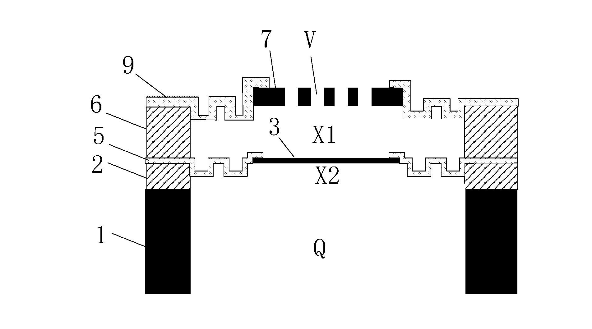
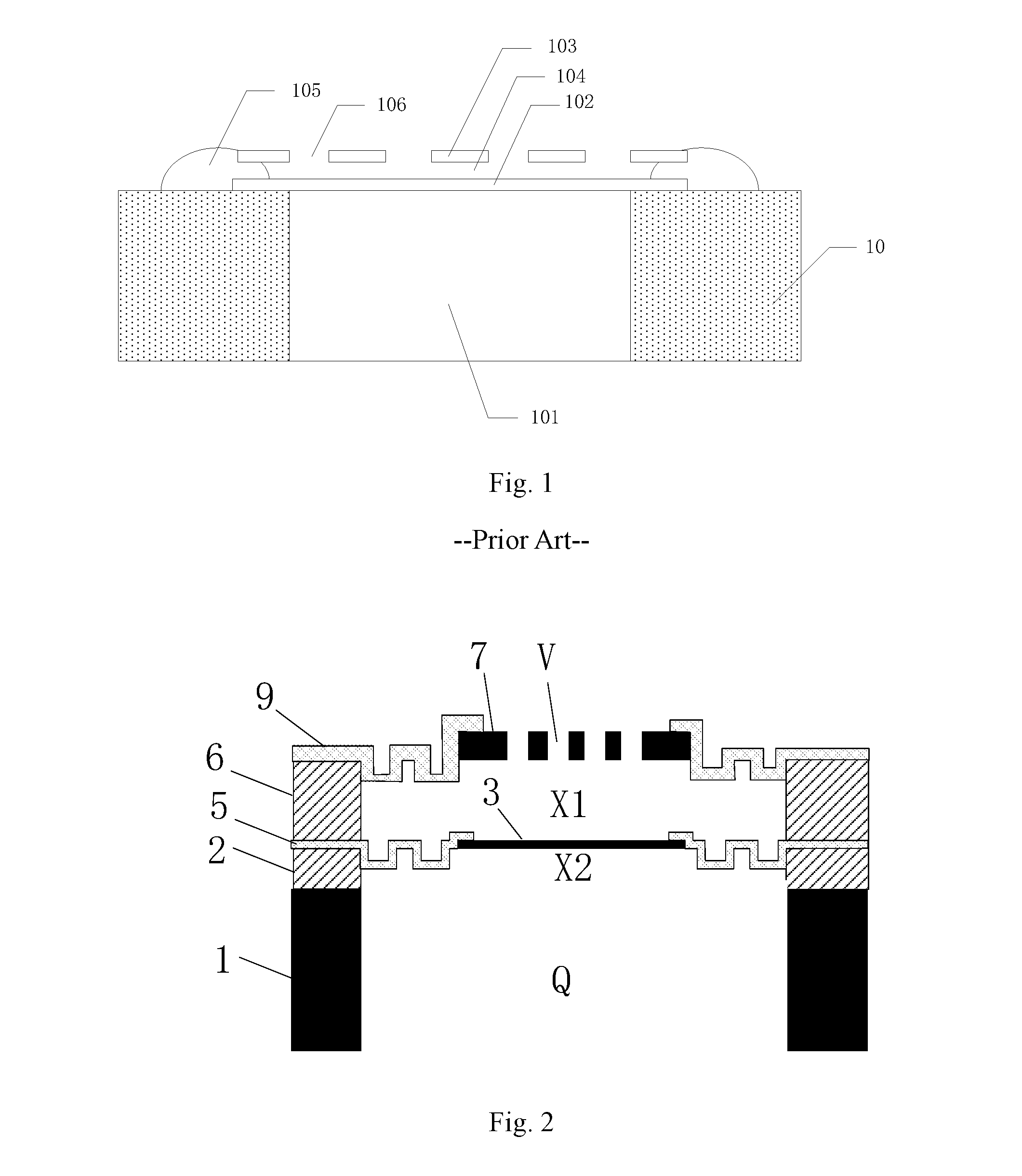
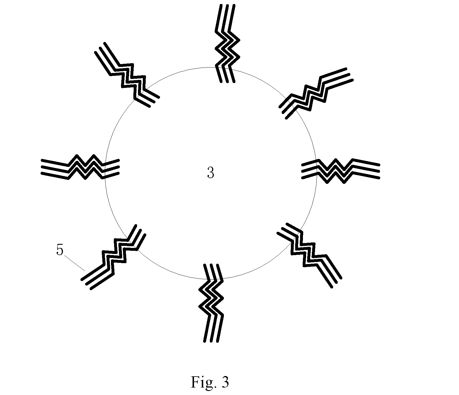
[0053]In the capacitive silicon microphone provided in the present invention, a first dielectric layer is set on a substrate with a back cavity, a lower polar plate is set over the back cavity, a first elastic member of which its inner edge is connected with the edge of the lower polar plate and its outer edge is located on the upper surface of the first dielectric layer, a second dielectric layer which is located on the outer edge of the first elastic member and right above the first dielectric layer, a upper polar plate which has a plurality of release holes and ...


PUM


Abstract

A capacitive silicon microphone comprises: a first dielectric layer sets on a substrate with a back cavity, a lower polar plate which is located over the back cavity, a first elastic member of which an inner edge is connected with the edge of the lower polar plate and an outer edge is located on the upper surface of the first dielectric layer, a second dielectric layer which is located on the outer edge of the first elastic member and right above the first dielectric layer, an upper polar plate which has a plurality of release holes and is formed above the lower polar plate with an air gap in between, a second elastic member of which an inner edge is connected with the edge of the upper polar plate and an outer edge is located on the upper surface of the second dielectric layer.

Description

CROSS-REFERENCE TO RELATED APPLICATION[0001]The application claims the priority benefit of International Patent Application Serial No. PCT / CN2014 / 087491, filed Sep. 26, 2014, which is related to and claims the priority benefit of China patent application serial No. 201310631540.5 filed Nov. 29, 2013. The entirety of each of the above-mentioned patent applications is hereby incorporated by reference herein and made a part of the specification.FIELD OF THE INVENTION[0002]The present invention relates generally to the semiconductor manufacturing technology, particularly to a capacitive silicon microphone and fabrication method thereof.BACKGROUND OF THE INVENTION[0003]With the rapid development of mobile communication technologies, the uses of communication devices such as smartphones, laptops and tablet computers by consumers are increasing; moreover, those electronic devices are becoming more functional while the size of which keeps getting smaller. Along the decrease of volume of ele...

Claims


Application Information

Patent Timeline
Patent Type & Authority Applications(United States)
IPC IPC(8): H04R7/20H04R19/00H04R7/08H04R19/04H04R31/00
CPCH04R7/20H04R19/04H04R31/003H04R31/006H04R2410/03H04R19/005H04R2231/003H04R2201/003H04R7/08H04R31/00
Inventor ZHAO, YUHANGWANG, YONGKANG, XIAOXUCHEN, YAN
Owner SHANGHAI INTEGRATED CIRCUIT RES & DEV CENT
Learn More