

Printed wiring board, method for producing printed wiring board and semiconductor device
a technology of printed wiring and wiring board, which is applied in the direction of printed circuit manufacturing, resist details, printed circuit aspects, etc., can solve the problems of poor discoloration resistivity to heat, the screen printing method cannot deal with fine patterning, and the resin composition of photosensitive resins is poor. , to achieve the effect of efficient production of printed wiring boards, excellent thermo-discoloration resistivity and patterning resolution, and high reliability
- Summary
- Abstract
- Description
- Claims
- Application Information
AI Technical Summary
Benefits of technology
Problems solved by technology
Method used
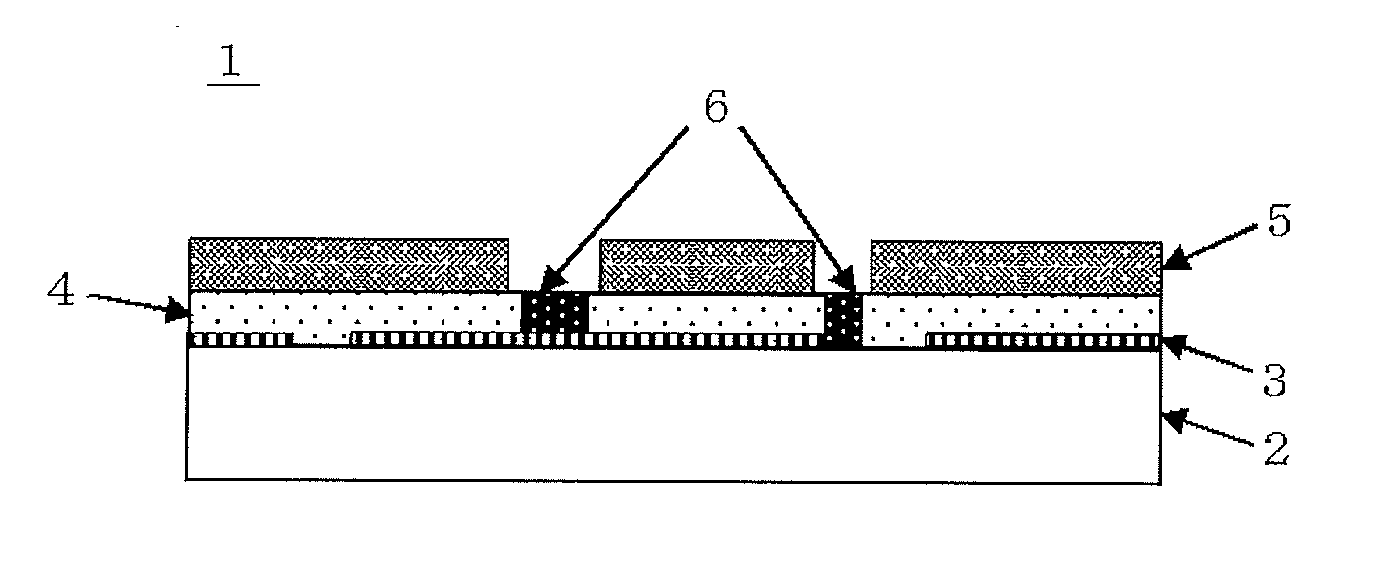
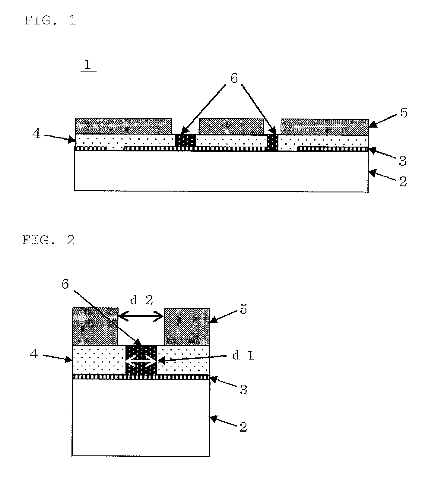
Image

Examples
preparation example 1
[0111]As organopolysiloxanes containing vinyl group, 50 g of (SiO2)1.0(Me2ViSiO0.5)1.0 and 50 g of dimethylpolysiloxane both terminals of which are blocked with vinyldimethyl-siloxy groups and having a viscosity of 100 Pa·s; as a polysiloxane containing SiH group (hydrogenpolysiloxane), 11 g of methylhydrogensilicone oil (trade name: KF-99, manufactured by Shin-Etsu Chemical Co. Ltd.); as an acetylene alcohol type reaction retarder, 0.2 g of ethynylmethyldecylcarbinol; and as a platinum group metal group based catalyst, 0.1 g of 1% by mass octyl alcohol solution of chloroplatinic acid; were blended, and well stirred to obtain a base composition. To this base composition, 6 g of diethylene glycol diethyl ether and 100 g of titanium dioxide (trade name: CR-90, average particle diameter: about 0.25 μm, manufactured by ISHIHARA SANGYO KAISHA, LTD.) were added as a solvent and a filler respectively, and kneaded with a three-roll mill to prepare a silicone resin composition (S1).
preparation example 2
[0112]As an organopolysiloxane containing vinyl group, 72 g of (PhSiO1.5)0.5(MeViSiO)0.2(Me2SiO)0.3; as a polysiloxane containing SiH group, 12 g of (PhSiO1.5)0.3(Me2HSiO0.5)0.7; as an acetylene alcohol type reaction retarder, 0.2 g of ethynylmethyldecylcarbinol; and as a platinum group metal group based catalyst, 0.1 g of 1% by mass octyl alcohol solution of chloroplatinic acid; were blended, and well stirred to obtain a base composition. To this base composition, 67 g of titanium dioxide (trade name: R-820, average particle diameter: about 0.26 μm, manufactured by ISHIHARA SANGYO KAISHA, LTD.) was added as a filler, and kneaded with a three-roll mill to prepare a silicone resin composition (S2).
preparation example 3
[0113]As an organopolysiloxane containing vinyl group, 100 g of (PhSiO1.5)0.45(Me2SiO)0.5(MeViSiO)0.025(Me2ViSiO0.5)0.025; as a polysiloxane containing SiH group, 100 g of (PhSiO1.5)0.45(Me2SiO)0.5(MeHSiO)0.05; as an acetylene alcohol type reaction retarder, 0.2 g of ethynylmethyldecyl-carbinol; and as a platinum group metal group based catalyst, 0.2 g of 1% by mass octyl alcohol solution of chloroplatinic acid; were blended, and well stirred to obtain a base composition. To this base composition, 15 g of diethylene glycol diethyl ether and 200 g of titanium dioxide (trade name: CR-90, average particle diameter: about 0.25 μm, manufactured by ISHIHARA SANGYO KAISHA, LTD.) were added as a solvent and a filler respectively, and kneaded with a three-roll mill to prepare a silicone resin composition (S3).
PUM
| Property | Measurement | Unit |
|---|---|---|
| particle diameter | aaaaa | aaaaa |
| particle diameter | aaaaa | aaaaa |
| particle diameter | aaaaa | aaaaa |
Abstract
Description
Claims
Application Information