Method of producing film
a film and film technology, applied in the field of film production methods, can solve the problems of easy disappearance of system deformation, inadequate adjustment of pull-down angle, etc., and achieve the effect of small number of die lines
- Summary
- Abstract
- Description
- Claims
- Application Information
AI Technical Summary
Benefits of technology
Problems solved by technology
Method used
Image
Examples
production example 1
Production of Glutarimide Acrylic Resin (A1)
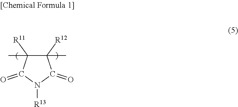
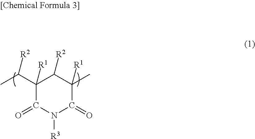
[0372]A glutarimide acrylic resin (A1) was produced using polymethylmethacrylate as a raw material resin and monomethylamine as an imidization agent.
[0373]In Production Example 1, a tandem-type reactive extruder was used, in which two extrusion reactors were connected in series.
[0374]The tandem-type reactive extruder had a first extruder and a second extruder, and both the extruders were intermeshing co-rotating twin screw extruders having a diameter of 75 mm and an L / D ratio (ratio of length (L) to diameter (D) of extruder) of 74. The raw material resin was supplied through the raw material supply port of the first extruder using a loss-in-weight feeder (manufactured by KUBOTA Corporation).
[0375]The pressure in each of the vents of the first and second extruders was reduced to about −0.090 MPa. Further, the first extruder was connected to the second extruder through a pipe having a diameter of 38 mm and a length of 2 m, and a constant flo...
production example 2
Production of Graft Copolymer (B1)
[0381]The following materials were fed into a polymerization apparatus having a capacity of 8 liters and equipped with a stirrer.
Deionized water200partsSodium polyoxyethylene lauryl ether phosphate0.45partSodium formaldehyde sulfoxylate0.11partDisodium ethylenediaminetetraacetate0.004partFerrous sulfate0.001part
[0382]Air in the polymerization apparatus was sufficiently purged with nitrogen gas so that there was virtually no oxygen in the polymerization apparatus. Then, the temperature in the polymerization apparatus was adjusted to 40° C., and 46.391 parts of a raw material mixture of acrylic rubber particles (B-1) shown in Table 2 was continuously added for 225 minutes. After 50 minutes from the start of the addition of (B-1), 0.2 part of sodium polyoxyethylene lauryl ether phosphate (sodium salt of polyoxyethylene lauryl ether phosphate (manufactured by TOHO CHEMICAL INDUSTRY Co., Ltd. under the trade name of PHOSPHANOL RD-510Y) was added to the p...
production example 3
Production of Graft Copolymer (B2)
[0385]The following materials were fed into a polymerization apparatus having a capacity of 8 liters and equipped with a stirrer.
Deionized water200partsSodium polyoxyethylene lauryl ether phosphate0.05partSodium formaldehyde sulfoxylate0.11partDisodium ethylenediaminetetraacetate0.004partFerrous sulfate0.001part
[0386]Air in the polymerization apparatus was sufficiently purged with nitrogen gas so that there was virtually no oxygen in the polymerization apparatus. Then, the temperature in the polymerization apparatus was adjusted to 40° C., and 45.491 parts of a raw material mixture of acrylic rubber particles (B-1) shown in Table 2 was continuously added for 225 minutes. After 20, 40, and 60 minutes from the start of the addition of (B-1), 0.2 part of sodium polyoxyethylene lauryl ether phosphate (sodium salt of polyoxyethylene lauryl ether phosphate (manufactured by TOHO CHEMICAL INDUSTRY Co., Ltd. under the trade name of PHOSPHANOL RD-510Y) was ad...
PUM
| Property | Measurement | Unit |
|---|---|---|
| Temperature | aaaaa | aaaaa |
| Fraction | aaaaa | aaaaa |
| Time | aaaaa | aaaaa |
Abstract
Description
Claims
Application Information
 - R&D
- Intellectual Property
- Life Sciences
- Materials
- Tech Scout
- Unparalleled Data Quality
- Higher Quality Content
- 60% Fewer Hallucinations
Browse by: Latest US Patents, China's latest patents, Technical Efficacy Thesaurus, Application Domain, Technology Topic, Popular Technical Reports.
© 2025 PatSnap. All rights reserved.Legal|Privacy policy|Modern Slavery Act Transparency Statement|Sitemap|About US| Contact US: help@patsnap.com


