Carbon dioxide capture and storage electrolytic methods

a technology of carbon dioxide and electrolysis, which is applied in the direction of diaphragms, separation processes, energy-based wastewater treatment, etc., can solve the problems of reducing only fossil fuel consumption and its associated carbon emission, reducing current treatment process energy intensive, and greenhouse gas (ghg)

Active Publication Date: 2016-12-15
UNIV OF COLORADO THE REGENTS OF
View PDF2 Cites 17 Cited by
  • Summary
  • Abstract
  • Description
  • Claims
  • Application Information

AI Technical Summary

Benefits of technology

[0011]In certain embodiments, the salt of the given cation is less soluble in the anolyte in the absence of the external voltage than in the presence of the external voltage. In other embodiments, the given cation is a polyvalent cation, such as but not limited to an alkaline earth cation. In yet other embodiments, the...

Problems solved by technology

Wastewater treatment is essential for preventing disease and protecting the environment, but current treatment processes are energy intensive and emit greenhouse gas (GHG) due to fossil fuel use and organic degradation.
However, these methods reduce only fossil fuel consumption and its associated carbon emission.
Conventional CCS consists of energy-intensive and costly CO2 separation, purification, compression, transportation, and injection underground.
Emerging membrane technologies minimize regeneration process and reduce environmental impacts, but system scale-up has been a challenge.
Generally, these are even more energy intensive and costly than point-source CO2 mitigation.
However, the process is energy consumptive, with non-optimized, experimental systems using 426 to 481 kJ per mole of CO2 consumed and sto...

Method used


Image

  • Carbon dioxide capture and storage electrolytic methods
  • Carbon dioxide capture and storage electrolytic methods
  • Carbon dioxide capture and storage electrolytic methods

Examples


example 1

Current Production and Buffer Capacity Formation (MECC Reactor 1)

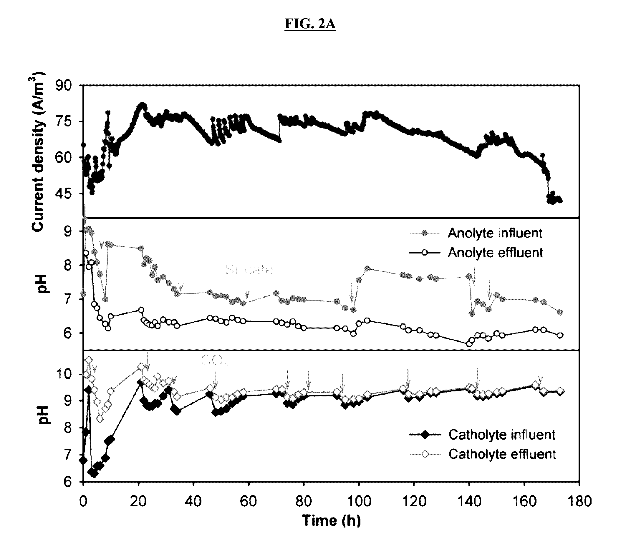
[0097]MECC reactors constructed according to MECC reactor construction 1 were operated in continuous-flow mode using both AW and PW. Despite a similar COD provided in both reactors, the maximum current generated from PW reached to 130 A / m3, which was 58% higher than the peak current from AW (FIGS. 2A-2C). Without wishing to be limited by any theory, this may be at least partially explained by the more than doubled conductivity of PW over the synthetic media. The current gradually dropped in the PW reactor, suggesting recalcitrant substrates in raw produced water inhibited the continued biodegradation. This is supported by the COD removal results: compared with nearly 100% COD removal in the AW, the COD removal in the PW was around 56%. Because a similar COD concentration was needed to perform the study, no produced water only control was performed. However, the same raw produced water was treated using a microbial capa...

example 2

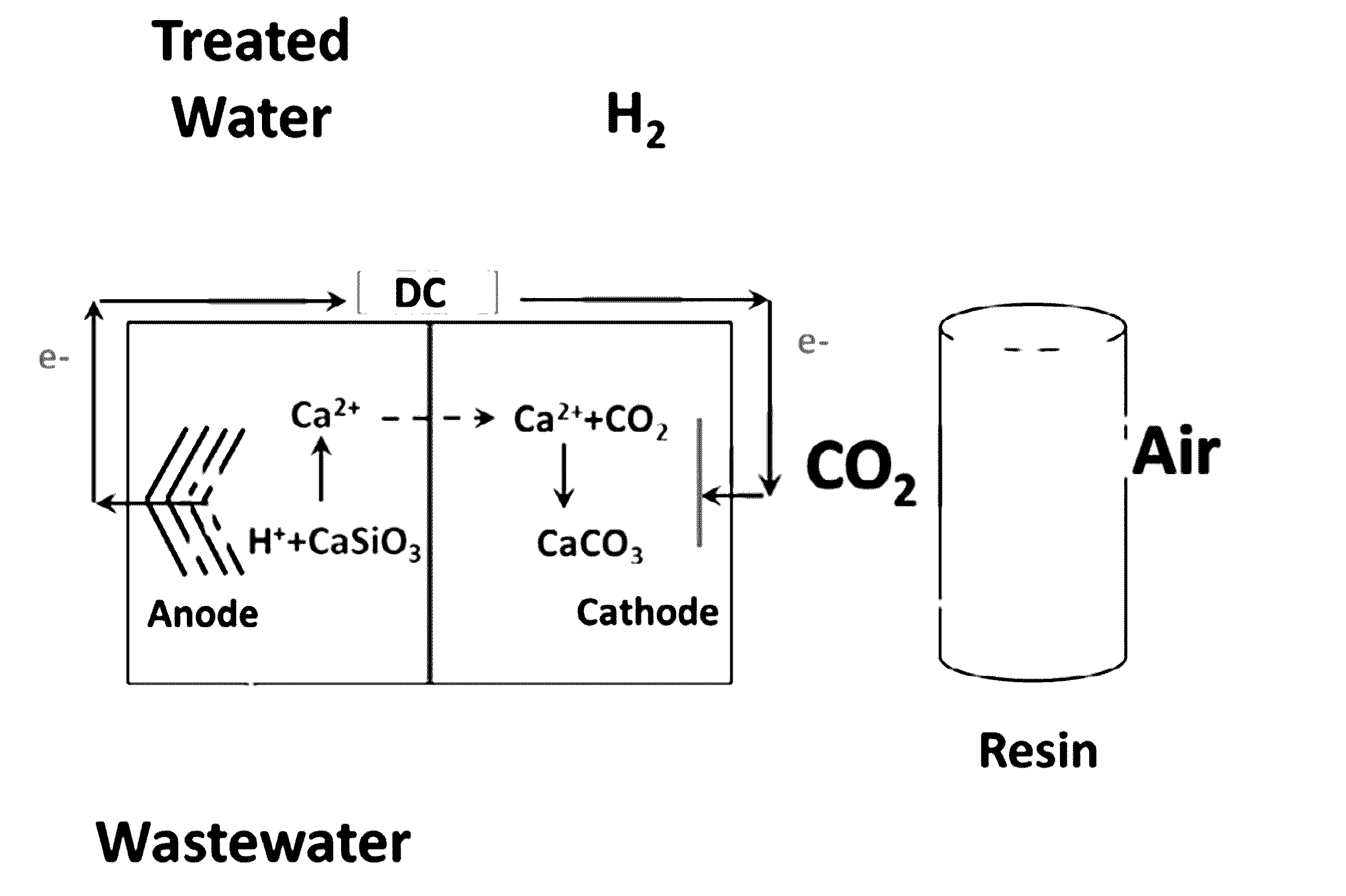
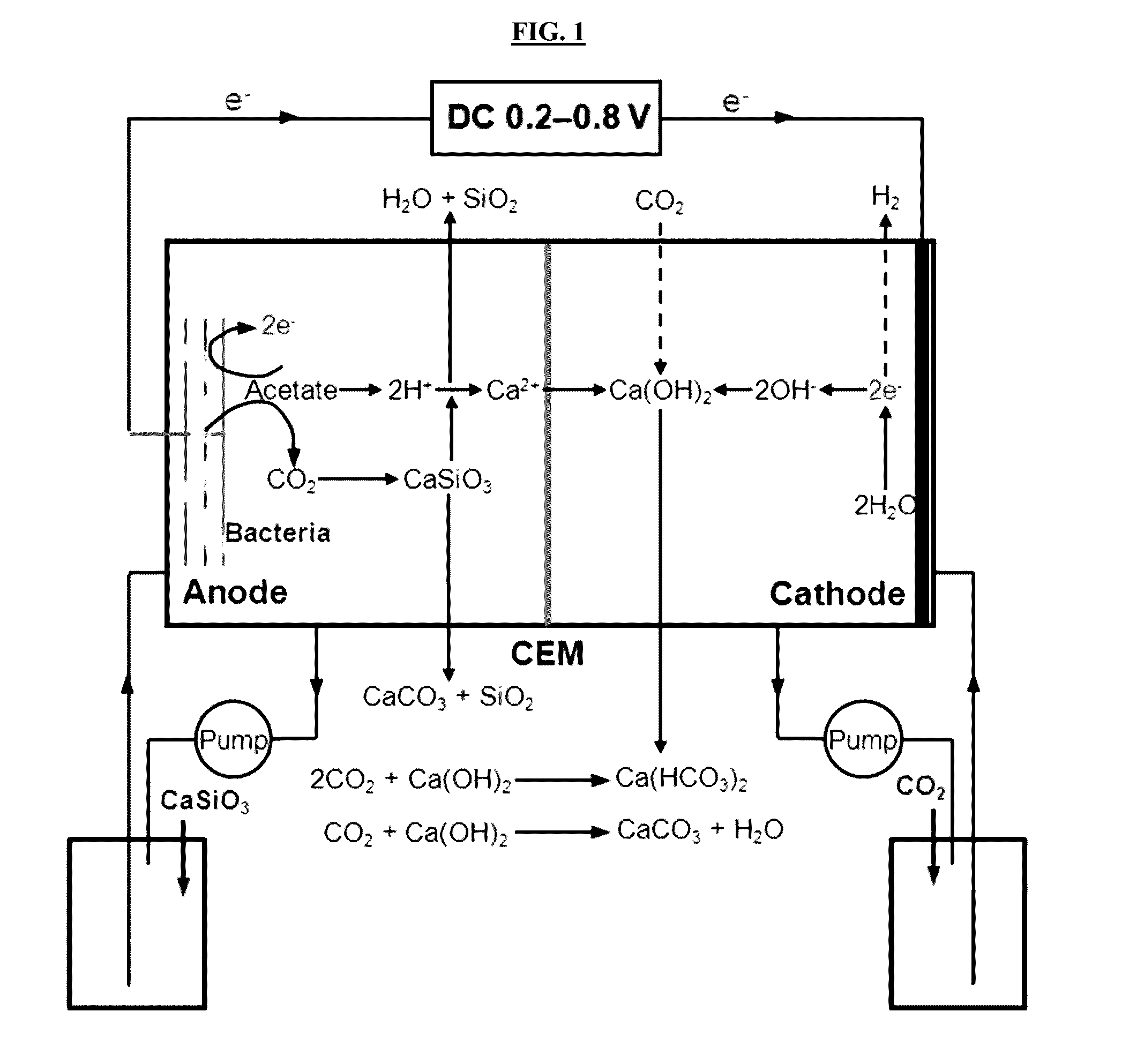
Carbon Capture Mechanism and Carbon Balance (MECC Reactor 1)

[0100]Compared with the abiotic control without applied voltage, a significant increase in Ca2+ concentration (from non-detectable to 497.0 mg / L) and Si content (from non-detectable to 112.5 mg / L) was observed in the anolyte of active MECC reactors, indicating microbially facilitated silicate dissolution from the paper support liberated cations for electrolytic reactions (Table 1). Meanwhile, the turbidity of catholytes increased due to the formation of white suspended solid in the liquid, and white precipitate accumulated on the wall and membrane surface facing the cathode (FIGS. 4A-4C). Both were identified as polymorphous CaCO3 by XRD quantitative crystalline phase analyses (Table 2). These results confirm that CO2 was captured and stored in MECCs in part by forming insoluble carbonate through the reaction with the cations derived from the silicate. Such direct precipitation of carbonate was not observed in a previous ab...

example 3

H2 Production and Energy Balance (MECC Reactor 1)

[0105]Continuous H2 was produced in the active reactors using either AW or PW electrolyte. High coulombic efficiencies (80-82%) for both electrolytes indicated that the majority of organic substrates were converted to current, which then was used to reduce H+ for H2 production with extremely high efficiencies with the cathodic H2 recovery ranged from 91-95% (Table 4). All of these lead to a high recovery of H2 yield (75-76%) of the theoretical maximum value. A higher H2 production rate was observed from the PW MECC due to the higher current density obtained from the reactor. No H2 was found in abiotic controls even with a same applied 325 voltage of 0.8 V.

[0106]Table 4 shows the preliminary energy balance of the MECC systems. The reactors consumed between 72-84 kJ of electrical energy for each mole CO2 captured (excluding pumping energy), which is a significant reduction compared with CCS-type systems. The energy savings was due to en...


PUM

PropertyMeasurementUnit
Fractionaaaaaaaaaa
Electric potential / voltageaaaaaaaaaa

Abstract

The present invention relates to the unexpected discovery of systems for capturing carbon dioxide and producing hydrogen gas. In certain embodiments, the system treats wastewater. In certain embodiments, the system captures and sequesters CO2 as carbonate salts.

Description

CROSS-REFERENCE TO RELATED APPLICATIONS[0001]The present application claims priority under 35 U.S.C. §119(e) to U.S. Provisional Patent Application No. 62 / 175,938, filed Jun. 15, 2015, which is incorporated herein by reference in its entirety.STATEMENT REGARDING FEDERALLY SPONSORED RESEARCH OR DEVELOPMENT[0002]This invention was made with government support under grant numbers CBET-1235848 and IIP-1445084 awarded by the U.S. National Science Foundation. The government has certain rights in the invention.BACKGROUND OF THE INVENTION[0003]Wastewater treatment is essential for preventing disease and protecting the environment, but current treatment processes are energy intensive and emit greenhouse gas (GHG) due to fossil fuel use and organic degradation. Every year, approximately 12 trillion gallons of municipal wastewater are treated by publicly owned treatment works in the U.S., and this consumes about 15 GW, or 3% of the total electricity produced in the U.S. In the meantime, approx...

Claims


Application Information

Patent Timeline
IPC IPC(8): C25B1/18C25B9/08C25B13/02C02F1/461C25B11/04C25B9/19
CPCC25B1/18C02F1/46176C25B11/0405C25B11/0442C02F2101/30C25B9/08C02F2001/46138C02F2303/26C02F2305/02C25B13/02Y02W10/33Y02W10/37B01D53/326B01D53/62C02F3/005B01D2251/404B01D2257/504C02F2103/08Y02C20/40Y02P20/151C25B9/19C25B11/051C25B11/073
Inventor REN, ZHIYONGLU, LU
Owner UNIV OF COLORADO THE REGENTS OF
Why Eureka
Try Eureka