
Microfluidic cartridge and reader device, system, and method of use

a microfluidic cartridge and reader technology, applied in the field of disposable microfluidic devices, can solve the problems of time delay in getting the test, lack of devices, and inability to run more complicated diagnostic tests, and achieve the effect of facilitating the potentiostat reader devi

Inactive Publication Date: 2017-01-19
KER JUSTIN R DR
View PDF2 Cites 21 Cited by
  • Summary
  • Abstract
  • Description
  • Claims
  • Application Information

AI Technical Summary

Benefits of technology

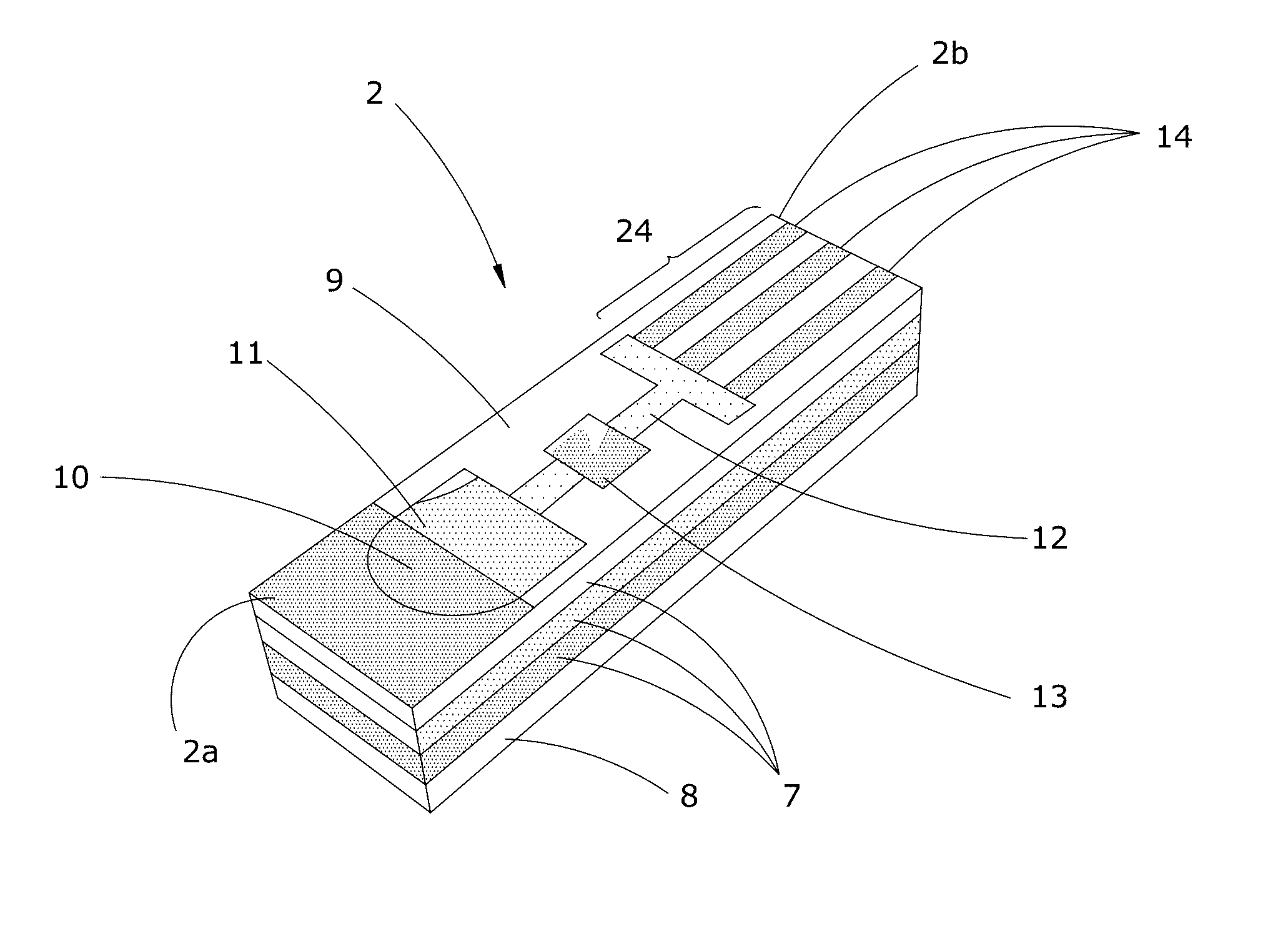
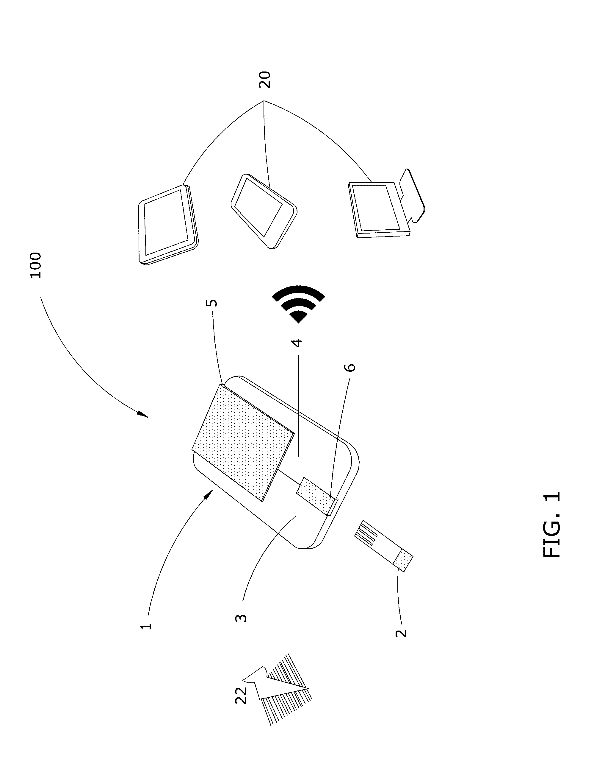
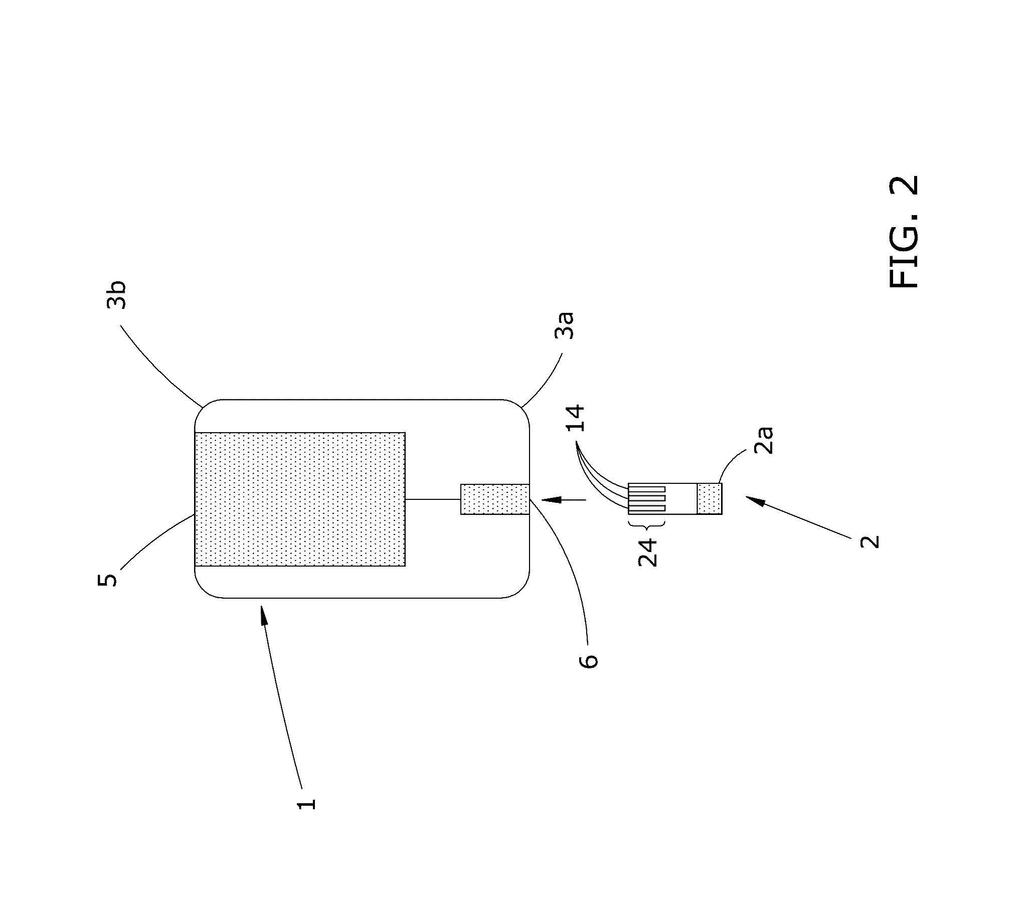
This patent describes a device that can detect and measure the concentration of analyte reaction products using electro-chemistry and electro-analytics. The device consists of an assay layer with a drop zone for receiving a patient specimen, a filter for removing contaminants, and a reaction chamber containing enzymes and reagents to react with the filtered specimen and produce analyte reaction products. A detection mechanism, such as three parallel electrodes, located at the front of the device can detect the presence and concentration of the analyte reaction products. The device is connected to a potentiostat reader device which facilitates the detection and quantification of the analyte reaction products. This embodiment reduces the cost of the device significantly by using disposable parts.

Problems solved by technology

Or, the physician may take the specimen, and have it transported to an outside laboratory for testing, which results in a time delay in getting the test results.
What these devices currently lack, though, is the ability to run more complicated diagnostic tests, such as testing for lipids, cholesterol, hemoglobin, liver enzymes, DNA, RNA, and proteins (e.g. antibodies) associated with a specific disease or disorder.
However, commercial available potentiostats are bulky and expensive, which limit their usage to professional laboratory experiments.

Method used


Image

  • Microfluidic cartridge and reader device, system, and method of use
  • Microfluidic cartridge and reader device, system, and method of use
  • Microfluidic cartridge and reader device, system, and method of use

Examples


Embodiment Construction

Glossary of Terms

[0052]As used herein, the term “Analyte” or “Analyte Reaction Product” refers to the proteins, polynucleotides (DNA), ribonucleotides (RNA) and / or bio-chemicals that are derived from the patient specimen and quantified by the potentiostat reader device 1. The analyte comprises a reaction product resulting from a chemical reaction that occurs within the cartridge reaction chamber between a filtered patient specimen and impregnate enzymes and / or reagents specifically designed for producing a desired analyte. By way of non-limiting examples, the analyte reaction product comprises one or more of: hemoglobin, platelets, sodium, potassium, creatinine, urea, lactic acid, cholesterol, low density lipoprotein, high density lipoprotein, triglycerides, testosterone, cortisol, prostate specific antigens, and tumor markers.

[0053]As used herein, the term “Electronic Computing Device” refers to any electronic computing device comprising a central processing unit (CPU), memory, and...


PUM

PropertyMeasurementUnit
frequencyaaaaaaaaaa
hydrophilicaaaaaaaaaa
concentrationaaaaaaaaaa

Abstract

Disposable microfluidic cartridges, potentiostat reader devices, systems, kits, and methods to determine the concentration of analyte reaction products in a patient's specimen, such as: blood, saliva, cerebrospinal fluid, joint fluid or tears. The microfluidic cartridges are disposable, paper-based strips comprising multiple assay layers, each layer comprising: a drop zone for receiving a patient specimen; a filter to remove contaminates, and / or isolate assay reactants; a hydrophilic microfluidic channel to direct movement of the specimen down the cartridge; a centered reaction chamber comprising impregnated enzymes and reagents to chemically react with the filtered specimen to produce an analyte; and a detector mechanism. Multiple analytes can be produced in parallel (e.g. one per layer), or sequentially along one layer. The detector mechanism utilizes electro-analytic methods to facilitate the reader device in quantifying each analyte, and each analyte concentration is wirelessly transmitted to an electronic computing device for storage in a patient's medical record.

Description

PRIORITY CLAIM[0001]This application claims priority to Provisional U.S. Patent Application Ser. No. 62 / 192,644 filed Jul. 15, 2015, entitled “MICROFLUIDIC CARTRIDGE AND READER DEVICE, SYSTEM, METHOD OF USE”, and which is hereby incorporated by reference in its entirety.FIELD OF THE DISCLOSURE[0002]The present disclosure generally relates to disposable microfluidic devices comprising cartridges (i.e. sensor strips) for point-of-care medical use to quickly analyze the concentration of an analyte in a patient's specimen, such as blood. The cartridges are inserted into a potentiostat reader device that calculates the amount or concentration of one or more analytes in the specimen.COPYRIGHT NOTICE[0003]A portion of the disclosure of this patent application document contains material that is subject to copyright protection. The copyright owner has no objection to the facsimile reproduction by anyone of the patent document or the patent disclosure, as it appears in the Patent and Trademar...

Claims


Application Information

Patent Timeline
Patent Type & Authority Applications(United States)
IPC IPC(8): B01L3/00G01N27/327G01N33/487G01N27/416
CPCB01L3/502715G01N27/4161G01N27/3272G01N27/3273G01N27/3275B01L2300/023B01L2300/0887B01L2300/0681B01L2300/0627B01L2300/0645B01L2300/021G01N33/48707B01L3/5023B01L3/5027B01L2300/0825B01L2200/141
Inventor KER, JUSTIN R.
Owner KER JUSTIN R DR
Learn More