
Decorative coatings for plastic substrates

Active Publication Date: 2017-01-19
SMR PATENTS S A R L +1
View PDF0 Cites 77 Cited by
  • Summary
  • Abstract
  • Description
  • Claims
  • Application Information

AI Technical Summary

Benefits of technology

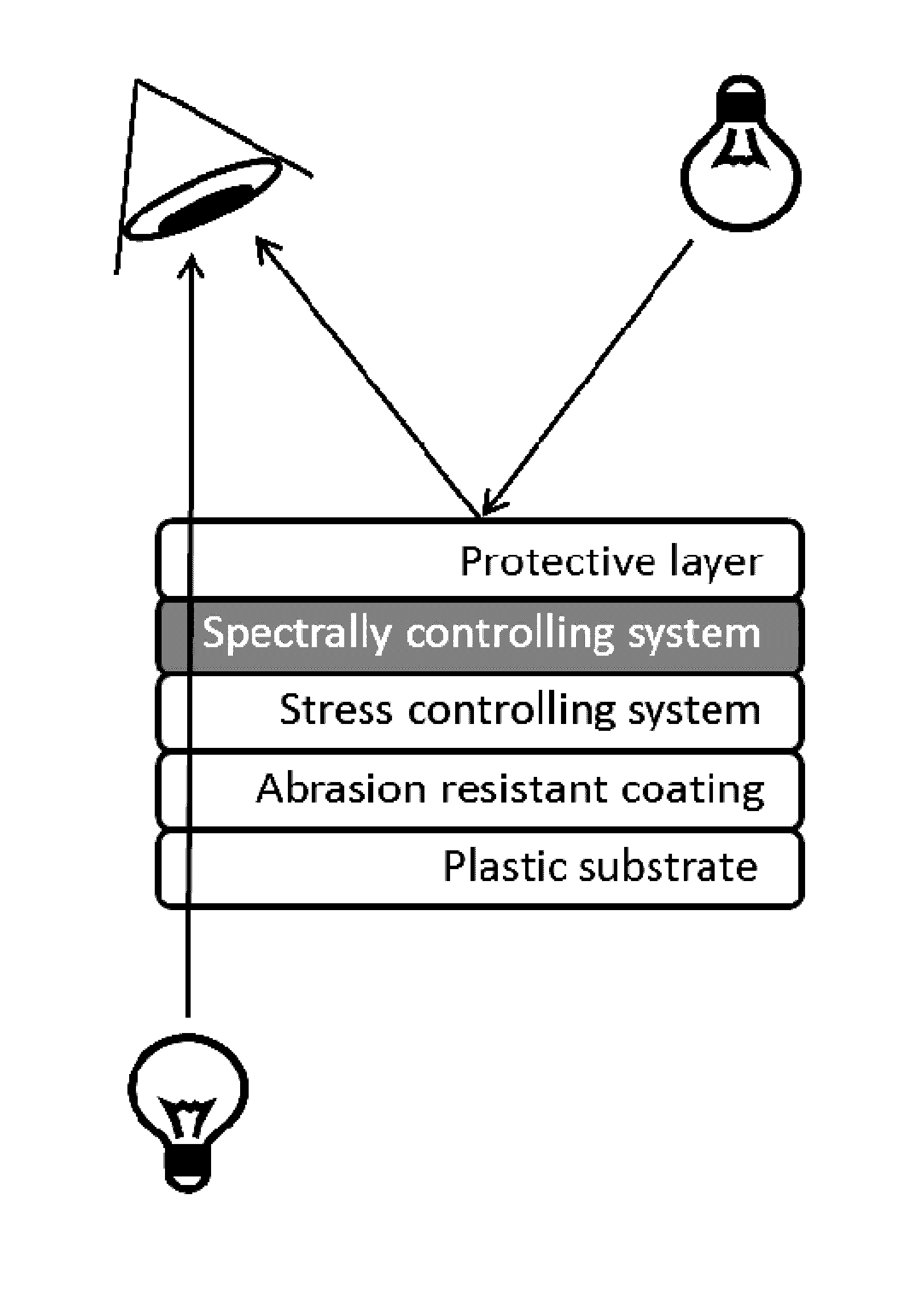
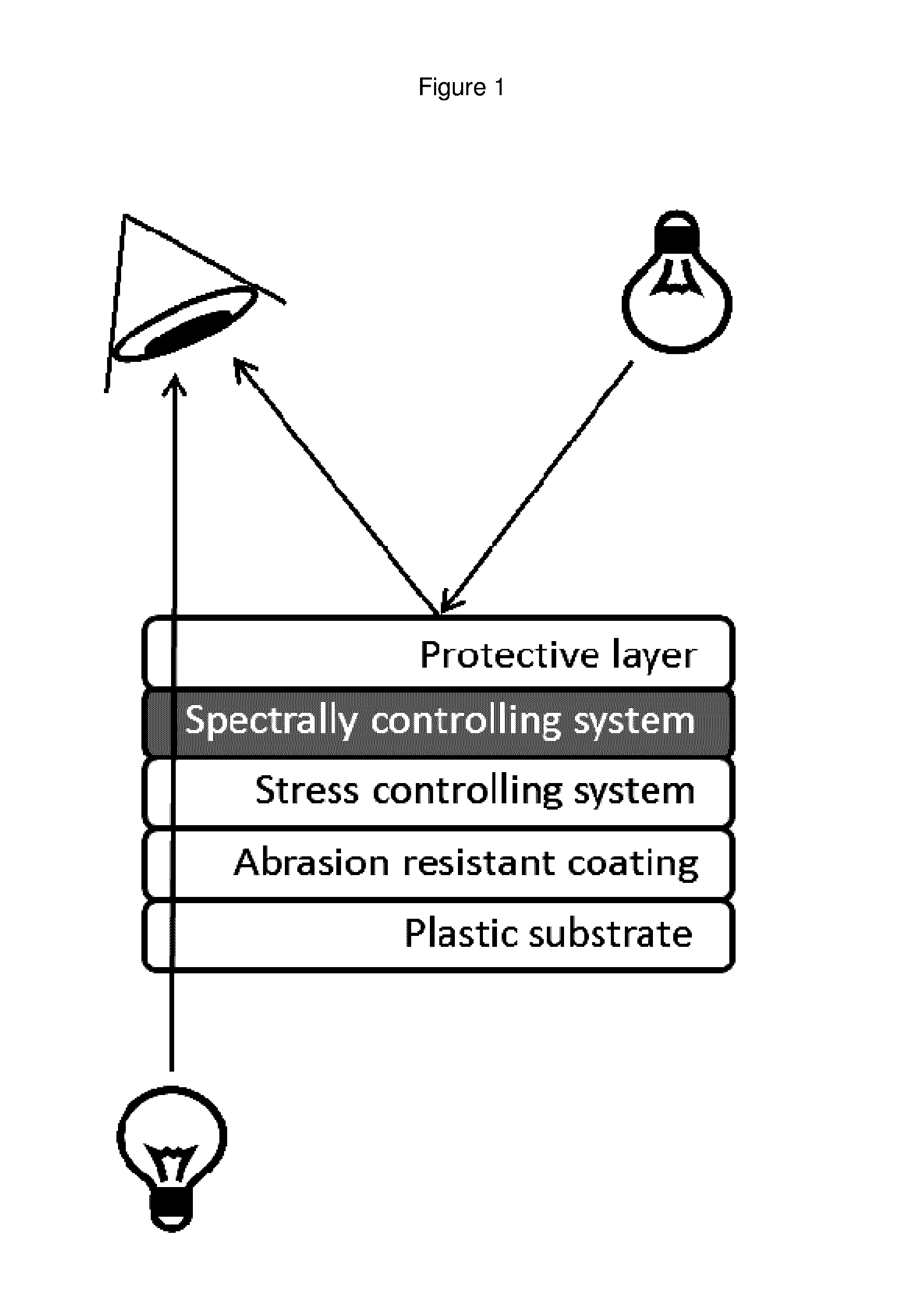
The spectrally controlling system described in the patent text can be used to modify how light is reflected and transmitted, resulting in a desired optical effect on a coated surface. By controlling the thickness of all layers in the system, including both absorbing and transparent layers, the system can achieve the desired reflected and transmitted color. The system can also be used to create illuminated patterns on plastic substrates, allowing for hidden lighting in products. When there is no rear illumination, the substrate appears uniform without any visible pattern.

Problems solved by technology

While bulk metal can be used for such applications, it is not only heavy and cumbersome to work with, but also difficult and expensive to machine and polish into the complex shapes that are common across these types of components.
In addition, bulk metal does not support ‘surprise and delight’ hidden lighting, or back lighting in general, nor does it lend itself to the formation of a surface where a part of the surface has a different appearance to another part of the surface.
While metal-look paints, film laminates and metallic inks offer options to create chrome-look surfaces on plastic substrates, they lack the authentic metal appearance that is required with these types of finishes and often show poor durability.
While these coatings offer high durability, they tend to be susceptible to issues with corrosion (Na, Mg or Ca salts) and electroplating itself utilises hazardous substances (such as Cr6+) that are not environmentally sustainable.
Furthermore, they lack the flexibility to cover all areas of the colour spectrum to offer wide customisation of colour tunability and depth of black on chrome.
For example, electroplaters offer tinted chromes that not only offer limited durability and colour fastness but are limited to specific areas of the colour spectrum, typically in the positive a* and b* colour space (in the CIELAB system) which is yellow in appearance.
Also, electroplating is completely opaque and does not support ‘surprise and delight’ hidden lighting, or back lighting in general.
However, such coatings are not physically and environmentally durable enough to survive even the most basic consumer testing requirements.
Indeed, none of the above metallic coatings possess tuneable properties to offer durable, decorative finishes that allow light transmission.
No such coatings offer the ability to converge the need for spectral and optical tunability with metallic finishes to create functional, highly durable, customisable chrome surfaces (for example) from bright through to deep black colours with backlighting functionality if desired.

Method used


Image

  • Decorative coatings for plastic substrates
  • Decorative coatings for plastic substrates
  • Decorative coatings for plastic substrates

Examples


example 1

Desired Optical Effect—Piano Black Spectrally Reflected Appearance with High % T

[0072]An injection moulded polycarbonate substrate is first cleaned through a commercial ultrasonic cleaning system with detergent. A final rinse in distilled water is required in a clean (dust free) environment. The substrate is then dip coated in a Momentive PHC-587B at a withdrawal rate of 10 mm / s. A flash-off time of 10 minutes allows solvents to slowly evaporate and the part to be largely tack free. The substrate is then moved to a curing oven for 45 minutes at 130° C. Subsequent coatings are performed within a 48 hour period so as to avoid aging / contamination of the hardcoating.

[0073]The substrate is loaded into a batch type vacuum sputter coater, (PylonMET VXL) which consists of a single coating chamber in which the samples are placed, evacuated and coated. Within this chamber the samples were evacuated to a pressure below 8 ×10⁻⁵mbar. There was a target to substrate distance of 110 mm and the fol...

example 2

Desired Optical Effect—Bright Chrome with High % T

[0079]A process generally as described in Example 1 is employed, with the following alterations.

[0080]Spectrally Controlling System

Layer 1Layer 2MaterialCrZrSiO2Thickness (nm)2515

[0081]The measured residual stress of layers was determined, the durability performance was tested, and the actual optical measurements obtained. The results are set out in Tables 4, 5 and 6 below.

TABLE 4Measured stress of the layersLayerStressStress controlling system−260 MPaTotal residual stress−160 MPa

TABLE 5Durability PerformanceTest DurationResultAbrasion resistance300cyclesAbrasion(Bayer)ratio = 15Thermal Shock200cyclesPassDry heat Test115°C.PassAccelerated UV2500kJ / m2Passweathering (SAE J1960)

TABLE 6Optical Measurement Data (Desired Optical Effect)Photopic reflectionY = 55.3%Photopic transmissionY = 7.2%Reflected colour target on transparentL* = 79.2substrate - CIE L*a*b* scale measured witha* = −0.8illuminant A / 2b* = 0.72Transmitted colour target on ...

example 3

Desired Optical Effect—Opaque Gun Metal (for Illuminated Patterns)

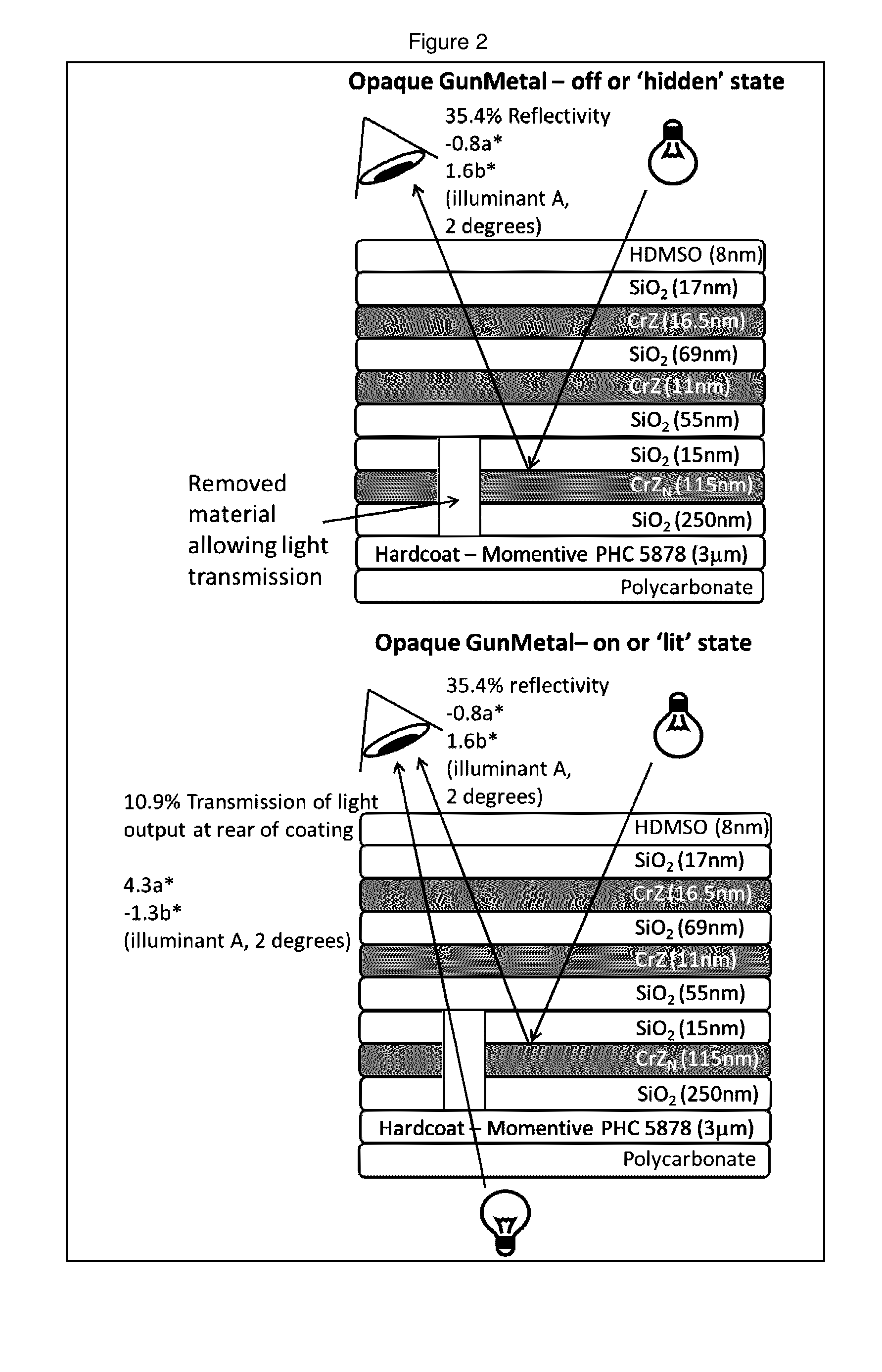
[0082]A process generally as described in Example 1 is employed, with the following alterations. However, it should also be noted that the sample is ‘vented’ between application of the stress controlling system and the spectrally controlling system for metal ablation / removal to enable the illuminated pattern (also referred to as “hidden 'til lit”) functionality. A schematic representation of a coated substrate in accordance with this embodiment is illustrated in FIG. 2.

[0083]Stress Controlling System

Layer 1Layer 2Layer 3Dual rotatablePower 35Power 31Silicon TargetkW @kW @99.90%27 kHz27 kHzChrome Zirconium—Power 60—Target 98.5% / 1.5%kWTotal Gas flowArgon 160Argon 150Argon 96sccmsccmsccmOxygen 302Nitrogen 90Oxygen 202sccmsccmsccmRPM8.42424Number of rounds3634 3Base Pressure2e−52e−52e−5(mbar)Run Pressure2e−32e−32e−3(mbar)Thickness (nm)250115 15

[0084]Spectrally Controlling System

Layer 1Layer 2Layer 3Layer 4Layer 5MaterialS...


PUM

PropertyMeasurementUnit
Nanoscale particle sizeaaaaaaaaaa
Transparencyaaaaaaaaaa
Stress optical coefficientaaaaaaaaaa

Abstract

The present invention relates to decorative coatings for plastic substrates, the decorative coatings ideally being stable and durable coatings that are spectrally tuneable to permit the selection of a variety of appearances, and ideally providing a decorative metal finish. More particularly the present invention provides for a plastic substrate having a decorative coating including a spectrally controlling system and a stress controlling system. The spectrally controlling system includes alternating absorbing layers and transparent layers, and the stress controlling system controls the overall residual stress of the decorative coating to within a desired range. Further provided are methods for applying to a plastic substrate a decorative coating having a spectrally controlling system and a stress controlling system.

Description

CROSS-REFERENCE TO RELATED APPLICATIONS[0001]This application is the National Phase of International Application PCT / AU2015 / 000093 filed Feb. 20, 2015 which designated the U.S. and that International Application was published in English on Sep. 11, 2015 as International Publication Number WO 2015 / 131223 A1. PCT / AU2015 / 000093 claims priority to Australian Provisional Application No. 2014900781, filed Mar. 7, 2014. Thus, the subject nonprovisional application claims priority to Australian Provisional Application No. 2014900781, filed Mar. 7, 2014. The disclosures of both applications are incorporated herein by reference.BACKGROUND OF THE INVENTION[0002]The present invention relates to decorative coatings for plastic substrates, the decorative coatings ideally being stable and durable coatings that are spectrally tuneable to permit the selection of a variety of appearances, including chrome tints, from a gun-metal grey to a piano black, or a brushed-metal look, ideally to provide a dec...

Claims


Application Information

Patent Timeline
IPC IPC(8): C08J7/04B05D1/02B05D1/30B05D1/18C08J7/043C08J7/046
CPCC08J7/045B05D1/18C08J2483/04B05D1/30C08J2369/00B05D1/02C09D1/00C09D5/00B05D5/06B05D7/02C23C14/0015C23C14/10C23C14/205C08J7/046C08J7/0423C08J7/043B32B15/08C08J7/06B32B2307/40B32B2307/402
Inventor HALL, COLIN JAMESEVANS, DREW RAYMONDFIELD, SIMON DAVIDCARUSO, DEAN
Owner SMR PATENTS S A R L
Learn More