Complex cleaning system for heat exchanger

a heat exchanger and complex technology, applied in the direction of indirect heat exchangers, flush cleaning, lighting and heating apparatus, etc., can solve the problems of corroding the rear facilities of the scr device, low denitrification efficiency of the sncr method, and reducing the activity of bisulfate, so as to achieve low pressure, reduce the amount of high-temperature steam, and reduce the effect of water content in the exhaust gas

Inactive Publication Date: 2017-01-19
GSCO
View PDF1 Cites 4 Cited by
  • Summary
  • Abstract
  • Description
  • Claims
  • Application Information

AI Technical Summary

Benefits of technology

[0026]The complex cleaning method according to the present disclosure may be conveniently performed during operation mode, namely, without suspension of plant operation which was a prior problem, and do not damage an air preheater or an electrostatic precipitator. Furthermore, spraying high-temperature steam has a lower pressure than that of spraying high-pressure water, and water amount for spraying the high-temperature steam is very small compared with spraying the high-pressure water, and as such, water content in an exhaust gas is not increased. Accordingly, additional waste water disposal facilities are not required because contaminants are not discharged additionally.
[0027]Meanwhile, CO2 collected from the exhaust gas of the power plant may be recycled to generate dry ice, thereby being advantageous in terms of utilization of CO2 and cost reduction.

Problems solved by technology

The SCR method is mainly used because the SNCR method has low denitrification efficiency.
Ammonium bisulfate decreases activity of catalyst, corrodes the rear facilities of the SCR device, and increases loss of pressure in the boiler due to blocking a hole for catalyst and a passage for the exhaust gas in the heat exchanger.
However, in spite of this limitation, during operation of the SCR device, a blocking problem in heat exchangers of various equipments occurs frequently.
Spraying the high-pressure water, however, damages a coating layer of the thermal element, and as such, the blocking problem in the air preheater becomes severe.
This may not be an effective cleaning method.
Generally, although the high-pressure water cleaning device has very high operation pressure of 150 kg / cm2 g to 200 kg / cm2 g, in a case of the severe blocking problem in the air preheater, even the pressure of 300 kg / cm2 g may be not enough to solve the blocking problem.
Furthermore, as shown in FIG. 2, when cleaning by using the high-pressure water, plenty of water may flow in following devices such as the electrostatic precipitator to damage them.
In this case, however, the damage by water may be not prevented fundamentally.
), and then ammonium bisulfate contracts due to a temperature difference between ammonium bisulfate and ambient air, thereby forming numbers of cracks thereof.
However, when the other contaminants occur due to a decline of fuel quality, it may be hard to remove these contaminants.
Accordingly, it is ineffective to remove the contaminants by only using the cleaning technique with the dry ice pellets.

Method used


Image

  • Complex cleaning system for heat exchanger
  • Complex cleaning system for heat exchanger
  • Complex cleaning system for heat exchanger

Examples


Embodiment Construction

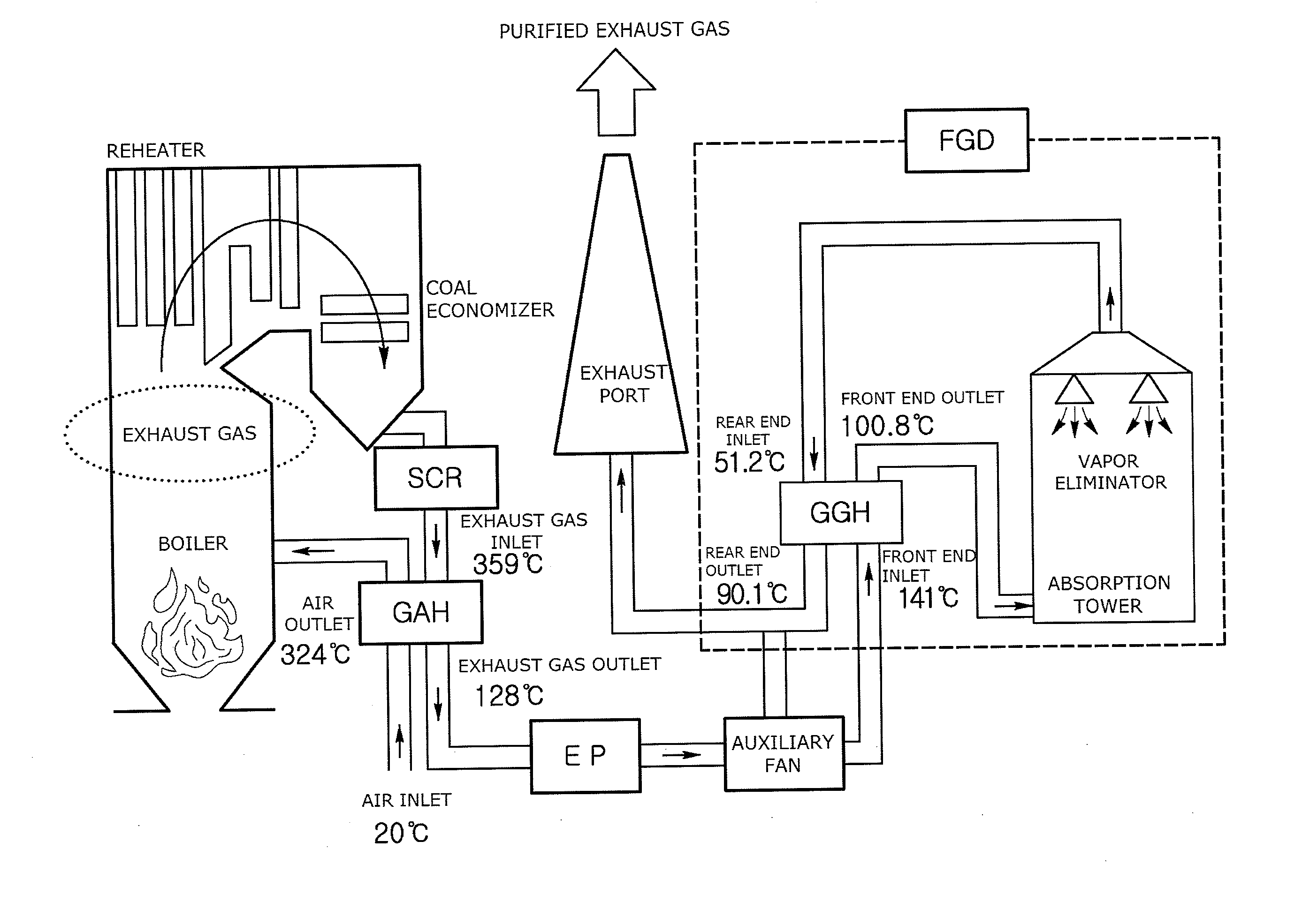
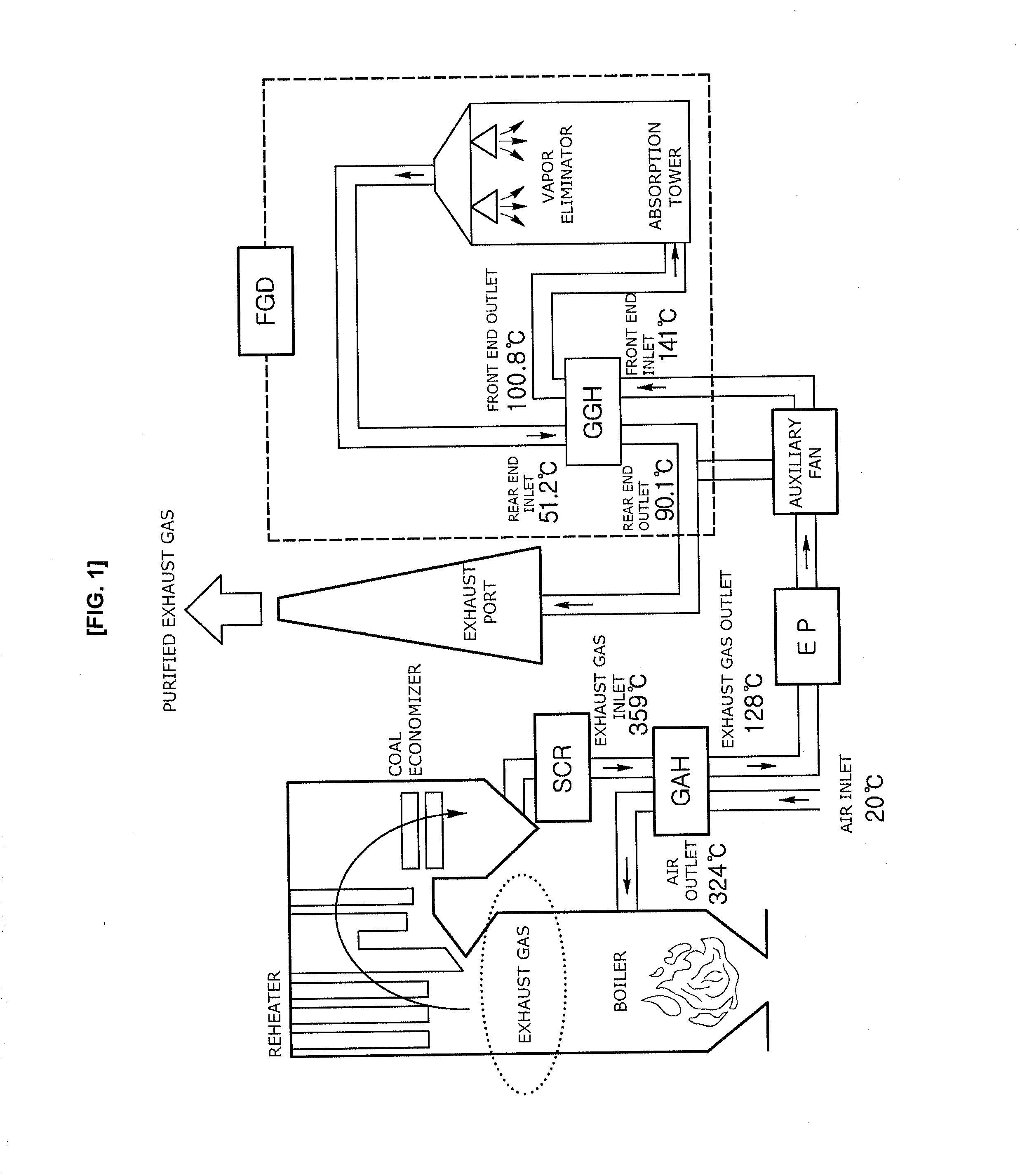
[0035]1: rotation direction of air preheater, 2: air preheater, 3: dry ice pellet spraying nozzle, 4: dry ice pellet spraying device, 5: dry ice pellet sizer, 6: high-temperature steam spraying device, 7: supply air outlet, 8: exhaust gas inlet, 9: supply air inlet, 10: exhaust gas outlet

BEST MODE

[0036]Hereinafter, the embodiments of the present disclosure will be described in detail with reference to accompanying drawings.

[0037]As shown in FIG. 5, dry ice pellets are sprayed from a cleaning device by air having a high-pressure or low-pressure to hit a surface of a thermal element of an air preheater. The dry ice pellets causes ammonium bisulfate to be rapidly frozen at ultralow temperature (−78° C.), such that ammonium bisulfate contracts due to a temperature difference with ambient temperature, thereby a number of cracks are occurred. The dry ice pellets penetrate into ammonium bisulfate through the cracks while sublimating to expand equal to or greater than 800 times in its volum...


PUM

PropertyMeasurementUnit
temperatureaaaaaaaaaa
diameteraaaaaaaaaa
speedaaaaaaaaaa

Abstract

The purpose of the present disclosure is to solve the problems of a difficult operation or occurrence of corrosion damage to equipment caused by the attachment of ammonium sulfate salt, which is generated when unreacted ammonia (NH3 slip) and sulfur trioxide (SO3) in exhaust gas are bonded with each other when a selective catalytic reduction (SCR) is used to eliminate nitrogen oxides that are contained in the exhaust gas generated during the combustion of a boiler or the like, to a heat exchanger of an air preheater (APH) or the like installed at the rear of an SCR device and blocks a passage of the exhaust gas such that the pressure inside the boiler is increased. To this end, a dry ice cleaning device is installed at the front of an exhaust gas inlet in an air preheater such that the blocking of a heat exchanger caused by ammonium sulfate salt or the like is removed by spraying dry ice pellets, and at the same time, high-temperature steam spraying device is installed at a cold end of the air preheater so as to spray the steam in the same direction as that of air supplied to a boiler, thereby removing contaminants more effectively. Furthermore, in order to effectively prevent blocking which occurs in a cold end of the air preheater, dry ice is sprayed to the front of an exhaust gas inlet of the air preheater and also, to the front of a supply air inlet of the air preheater which is an opposite direction thereof, such that a cleaning effect is increased.

Description

TECHNICAL FIELD[0001]The present disclosure relates to a method of cleaning a heat exchanger, and more particularly, to a complex cleaning system for the heat exchanger, which is to solve the problems of a difficult operation or shutdown caused by the attachment of ammonium bisulfate, which is generated when unreacted ammonia and sulfur trioxide in exhaust gas are bonded with each other when a selective catalytic reduction (SCR) method is used to eliminate nitrogen oxide that are contained in the exhaust gas generated during combustion of a boiler or the like, to a heat exchanger of an air preheater or the like installed at the rear of the SCR device and blocks a passage of the exhaust gas.BACKGROUND ART[0002]Nitrogen oxide, as a pollutant causing environmental harm, which is contained in the exhaust gas generated when coal, oil, gas, or combustible materials, etc. burn in a combustion engine, should be eliminated before being exhausted in air.[0003]To eliminate nitrogen oxide conta...

Claims


Application Information

Patent Timeline
Patent Type & Authority Applications(United States)
IPC IPC(8): F28G1/12F28D21/00F28D19/04
CPCF28G1/12F28D2021/0024F28D21/001F28D19/042B24C1/003F28G1/163F28G9/005Y02P70/10F28G3/16F28G9/00
Inventor KIM, DAE WOOKIM, DO JEUNGLEE, TAE-HEEJAEONG, SONG-YLKIM, DONG-WONJOO, SAE-ROM
Owner GSCO
Why Eureka
Try Eureka