Preparation of specimen arrays on an em grid

a specimen array and em grid technology, applied in the field of specimen array preparation on an em grid, can solve the problems of large number of grid trials, large volume of often very precious sample material waste, cumbersome procedure, etc., and achieve the effect of high throughput screening

Active Publication Date: 2017-01-26
THE SCRIPPS RES INST
View PDF15 Cites 4 Cited by
  • Summary
  • Abstract
  • Description
  • Claims
  • Application Information

AI Technical Summary

Benefits of technology

[0006]It is an object of the invention to provide methods and compositions preparation of complex specimen arrays for analysis by electron microscopy. These methods and compositions can permit high throughput screening of samples on single EM grid supports using sample volumes in the nanoliter and picoliter range (required for rare and difficult to obtain samples). Because picoliter scale volumes will not cover an entire EM sample grid surface under achievable contact angles, each EM sample grid may be processed to provide an array of specimen locations on a single grid.
[0017]The inkjet method is a method in which a solution of interest is placed in an extra-fine nozzle, pressure or heat is instantaneously applied on a portion near the nozzle's tip to correctly eject an extremely low volume of aqueous material from the nozzle's tip and directed to the surface of the EM grid. For example, the inkjet head may be a bubble-jet head having a mechanism for discharging a solvent with the application of thermal energy; a piezo-jet head that ejects a solution using a piezoelectric element; etc. Preferably, the drop dispenser comprises multiple nozzles that can be used to “print” sample volumes, wash solutions, stains, etc., onto the discretely addressable sample locations of the EM sample grid. When the aqueous solution is ejected from the inkjet head, each droplet forms a circular spot, the thickness and expansion of which is controlled by the structure of the EM grid surface. Connection with an adjacent spot can be effectively prevented even when the spots of sample solution are spotted in high density. On a standard ˜3 mm diameter EM grid (2 mm diameter imaging area), when the dispensed spots are 50-300 μm in diameter, transfer of the entire contents of the 12, 24, 48, 96 or 384 well-plate is possible.
[0024]The present invention is particularly applicable to transmission electron microscopy. Transmission electron microscopy (TEM) is a microscopy technique whereby a beam of electrons is transmitted through an ultra thin specimen, interacting with the specimen as it passes through. An image is formed from the interaction of the electrons transmitted through the specimen; the image is magnified and focused onto an imaging device, such as a fluorescent screen, on a layer of photographic film, or to be detected by a sensor such as a CCD camera. The image is in effect assumed to be a simple two-dimensional projection of the sample down the optical axis.

Problems solved by technology

EM sample preparation typically requires a cumbersome procedure of obtaining several negative stained samples on EM grid supports for each condition.
This results in a large number of grid trials, which entail loading individual grids into the electron microscope for analysis of each condition, and wastes large volumes of what are often very precious sample material.

Method used


Image

  • Preparation of specimen arrays on an em grid
  • Preparation of specimen arrays on an em grid
  • Preparation of specimen arrays on an em grid

Examples


Embodiment Construction

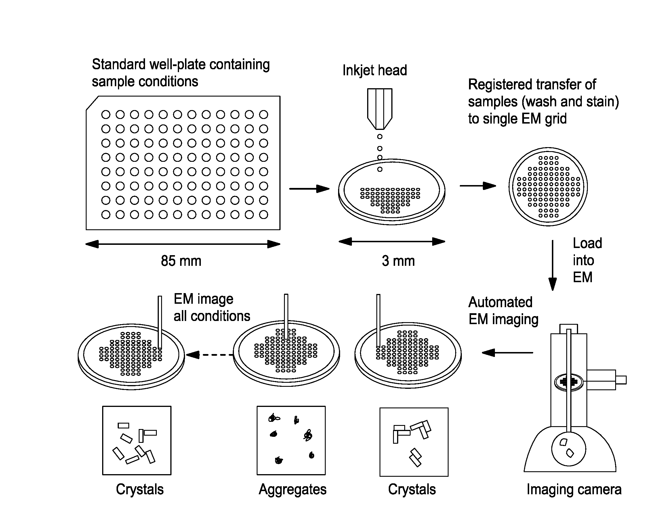
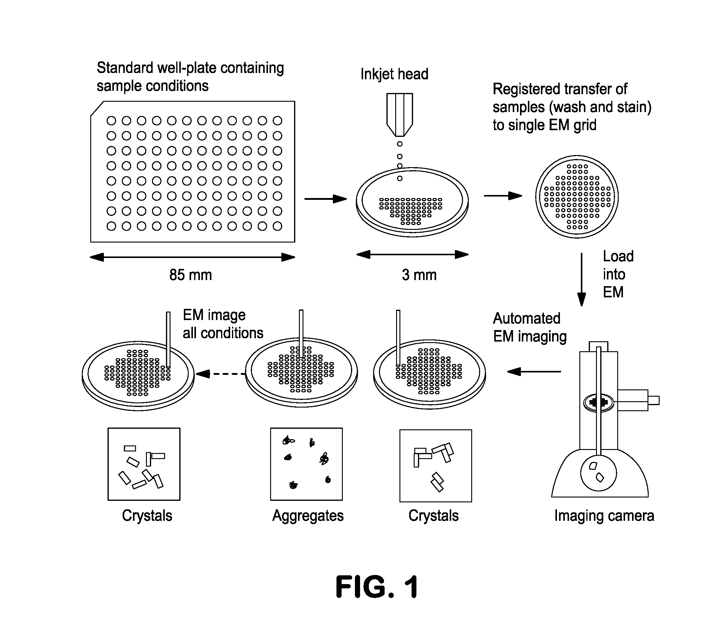
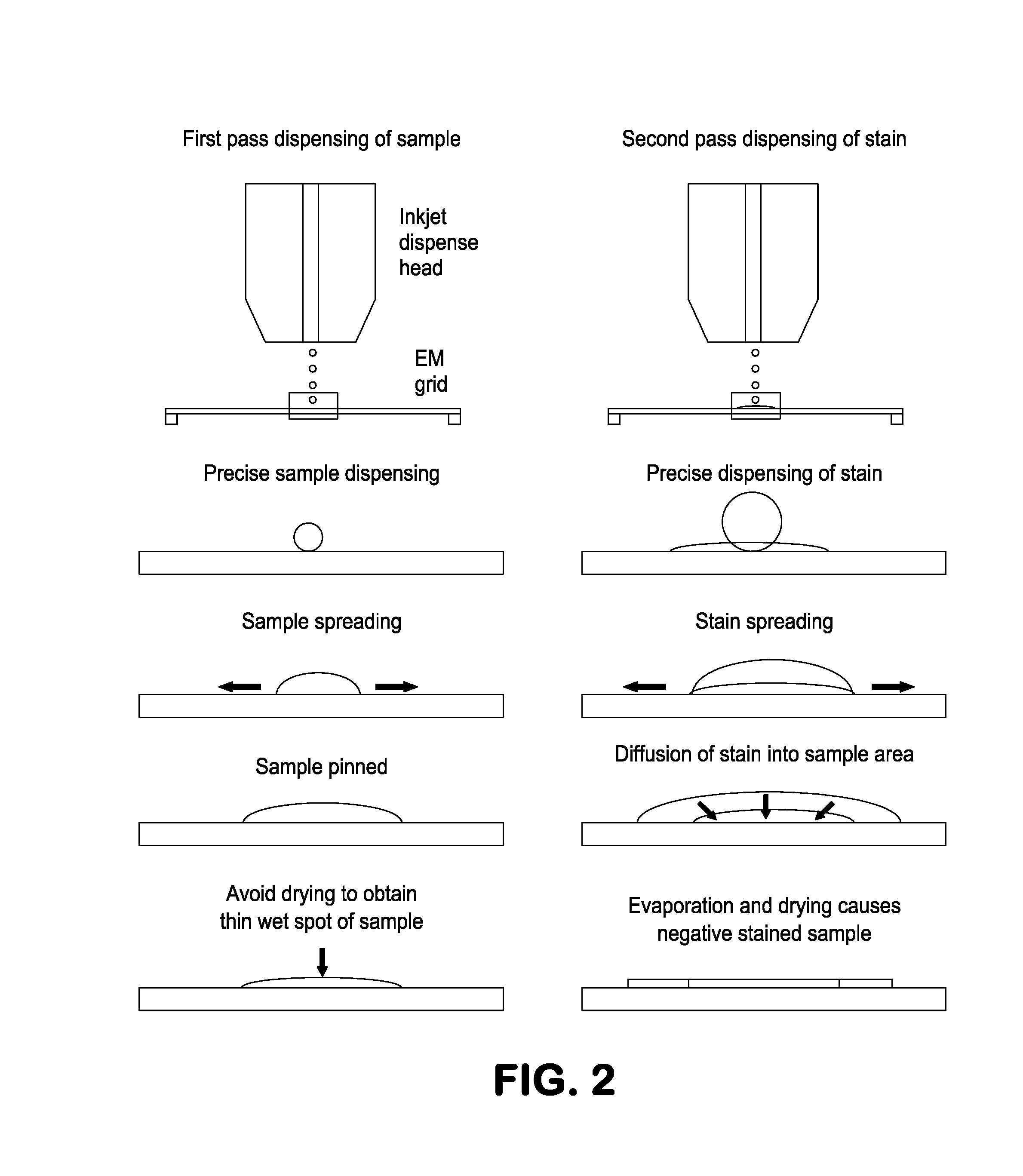
[0029]Molecular microscopy is a non-invasive molecular imaging technology that uses advanced specimen preparation and imaging methods designed specifically to visualize complex biological samples, under conditions close to their native state. For well-ordered samples such as viruses, and virus-antibody complexes, the achievable resolution can be <0.4 nm. High-throughput molecular microscopy combines robotic instruments, automated data collection and processing software, and a relational database into a pipeline to prepare, image, and analyze samples in a reproducible manner and with throughputs capable of addressing biopharmaceutical characterization needs in a statistically significant manner. Samples are preserved in solution by vitrification (using an automated cryogenic robot) or by negative stain, and then imaged using a transmission electron microscope (TEM) controlled by automated software that enables sampling of a significant portion of the specimen. Data is analyzed and st...


PUM

PropertyMeasurementUnit
thickaaaaaaaaaa
thickaaaaaaaaaa
diameteraaaaaaaaaa

Abstract

The invention provides systems or apparatuses for dispensing aqueous materials for electron microscopy (EM). The systems allow dispensing of aqueous materials onto an EM sample grid at individual specimen locations in an ordered array of specimen locations, with each individual specimen location in the array of locations. The systems contain a holder for reversibly receiving an EM sample grid, and a dispenser containing one or more dispensing elements that are configured to discretely dispense one or more aqueous solutions from the dispensing elements onto a plurality of individual specimen locations. The dispenser is able to provide an ordered array of discrete specimen locations discontinuous with one another. In the systems, at least one dispensing element is configured to dispense picoliter volumes of one or more of the aqueous solutions. Additionally, the systems contain a drive mechanism to position the EM sample grid relative to the one or more dispensing elements, as well as one or more reservoirs operably linked to the dispenser for holding the one or more aqueous solutions to be discretely dispensed onto each individual specimen location in the array of locations.

Description

CROSS-REFERENCE TO RELATED APPLICATIONS[0001]The subject patent application is a divisional of U.S. patent application Ser. No. 14 / 372,274, filed Jul. 15, 2014 (now pending), which is a national stage application of International Application No. PCT / US2013 / 000018, filed Jan. 14, 2013 (now abandoned), which claims the benefit of priority to U.S. Provisional Patent Application No. 61 / 632,046, filed Jan. 17, 2012 (now expired). The full disclosures of the priority applications are incorporated herein by reference in their entirety and for all purposes.STATEMENT OF GOVERNMENT SUPPORT[0002]This invention was made with government support under RR017573 awarded by the National Institutes of Health. The government has certain rights in the invention.BACKGROUND OF THE INVENTION[0003]The following discussion of the background of the invention is merely provided to aid the reader in understanding the invention and is not admitted to describe or constitute prior art to the present invention.[00...

Claims


Application Information

Patent Timeline
Patent Type & Authority Applications(United States)
IPC IPC(8): H01J37/26H01J37/20G01N1/31
CPCH01J37/261G01N1/312H01J37/20H01J2237/208H01J2237/204H01J2237/2007H01J2237/202G01N1/2813G01N1/30G01N1/31H01J2237/20G01N1/28H01J2237/2602
Inventor CARRAGHER, BRIDGETPOTTER, CLINTON S.JAIN, TILAK
Owner THE SCRIPPS RES INST
Why Eureka
Try Eureka