Method for electrolytic recycling and regenerating acidic cupric chloride etchants

a technology of acidic cupric chloride and electrolysis, which is applied in the direction of process efficiency improvement, printed circuit manufacturing, electrolysis components, etc., can solve the problems of overflow of excess etching, slow down the etching rate, and non-compliance with industrial production requirements, so as to reduce environmental impact, improve manufacturing safety, and consume less raw materials.

Active Publication Date: 2017-03-02
YE YITING
View PDF5 Cites 12 Cited by
  • Summary
  • Abstract
  • Description
  • Claims
  • Application Information

AI Technical Summary

Benefits of technology

[0009]The present invention aims at providing a method for electrolytic recycling and regenerating acidic cupric chloride etchants. In the said method, most chlorine g...

Problems solved by technology

In the above-mentioned etching process, the continuous charging of oxidant, water and sub-etchant inevitably results in an overflow of excess etchant from the etching tank, forming the so-called “etchant waste”.
This precipitate greatly slows down etching rate to a point that industrial production requirements are not met.
Consequentially, Cu(I) ion concentration in the etchant waste is low, and most of the chlorine gas from electrolysis does not have sufficient time to react with Cu(I) ions before escaping to the atmosphere, i.e. the electrolyte is unable to fully absorb and consume the large amount of poisonous chlorine gas produced in electrolysis.
This method requires a large amount of sodium hydroxide for chlorine treatment, and the chlorine gas cannot be reused.
In this method, although some chlorine gas can be reused, there still remains a substantial amount of unreacted chlorine gas and HCl gas due to the high concentration of volatile HCl and low concentration of Cu(I) ions in the etchant waste.
When both installed indoors, the two spray absorption towers undesirably take up much workspace.
If one or both spray absorption towers are installed outdoors, long ...

Method used


Image

  • Method for electrolytic recycling and regenerating acidic cupric chloride etchants
  • Method for electrolytic recycling and regenerating acidic cupric chloride etchants
  • Method for electrolytic recycling and regenerating acidic cupric chloride etchants

Examples


embodiment 1

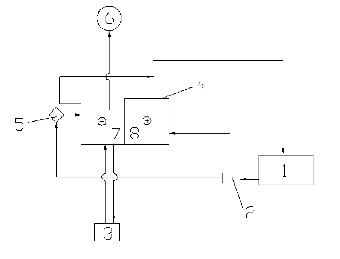
[0083]The electrolysis electrolytic recycling and regenerating apparatus used in this embodiment is illustrated in FIG. 1.

(1) In combination with the method above, according to the designated components and their mixing ratios as shown in Table 1 and 2 below, the etchant was prepared and the automatic detection and charging control machine was set up, and the etching operated was started. Etchant tank 1 was connected to the vacuum fluidic aerating device (not shown in FIG. 1); the vacuum fluidic aerating device comprises a liquid intake pipe, an acid-resistant pump, an air duct connected to the liquid intake pipe close to the acid-resistant pump, and a liquid outlet pipe; both the liquid intake pipe and the liquid outlet pipe were connected to the etching tank.

(2) The etchant waste overflowed from etchant tank 1 was collected and treated by water-oil separator 2; the etchant waste contained products of copper-etching, such as ferrous chloride and cuprous chloride.

(3) The treated etc...

embodiment 2

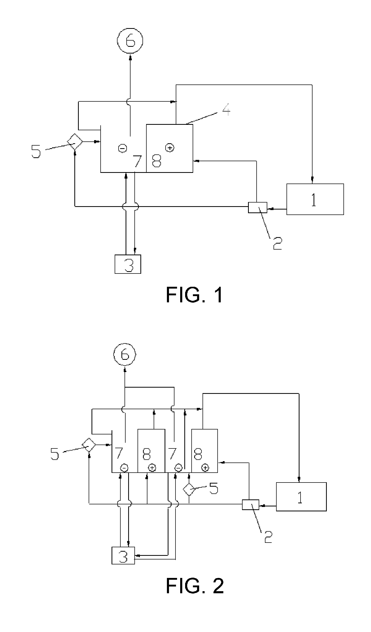
[0085]The electrolytic recycling and regenerating apparatus employed in this embodiment is illustrated in FIG. 2. Main differences between FIG. 2 and FIG. 1 are as follows: the electrolysis tank in FIG. 2 was separated by three electrolytic diaphragms into four chambers, which includes two cathode chambers 7 and two anode chambers 8. A cathode board is installed in each cathode chamber, and an anode board is installed in each anode.

[0086]The four chambers operate simultaneously during electrolysis.

[0087]The electrolytic recycling and regenerating method of this embodiment was the same as embodiment 1, except that:

(1) the etchant tank was not connected to the vacuum fluidic aerating device;

(2) the electrolytes from the cathode chamber 7 and anode chamber 8 were separately transferred to the etchant tank via two liquid outlet pipes.

[0088]The aqueous oxidant mixture used in the embodiment was comprised of 25 wt % of NaClO3, 12 wt % of NH4Cl, 1 wt % of NaCl, and 62 wt % of water.

[0089]T...

embodiment 3

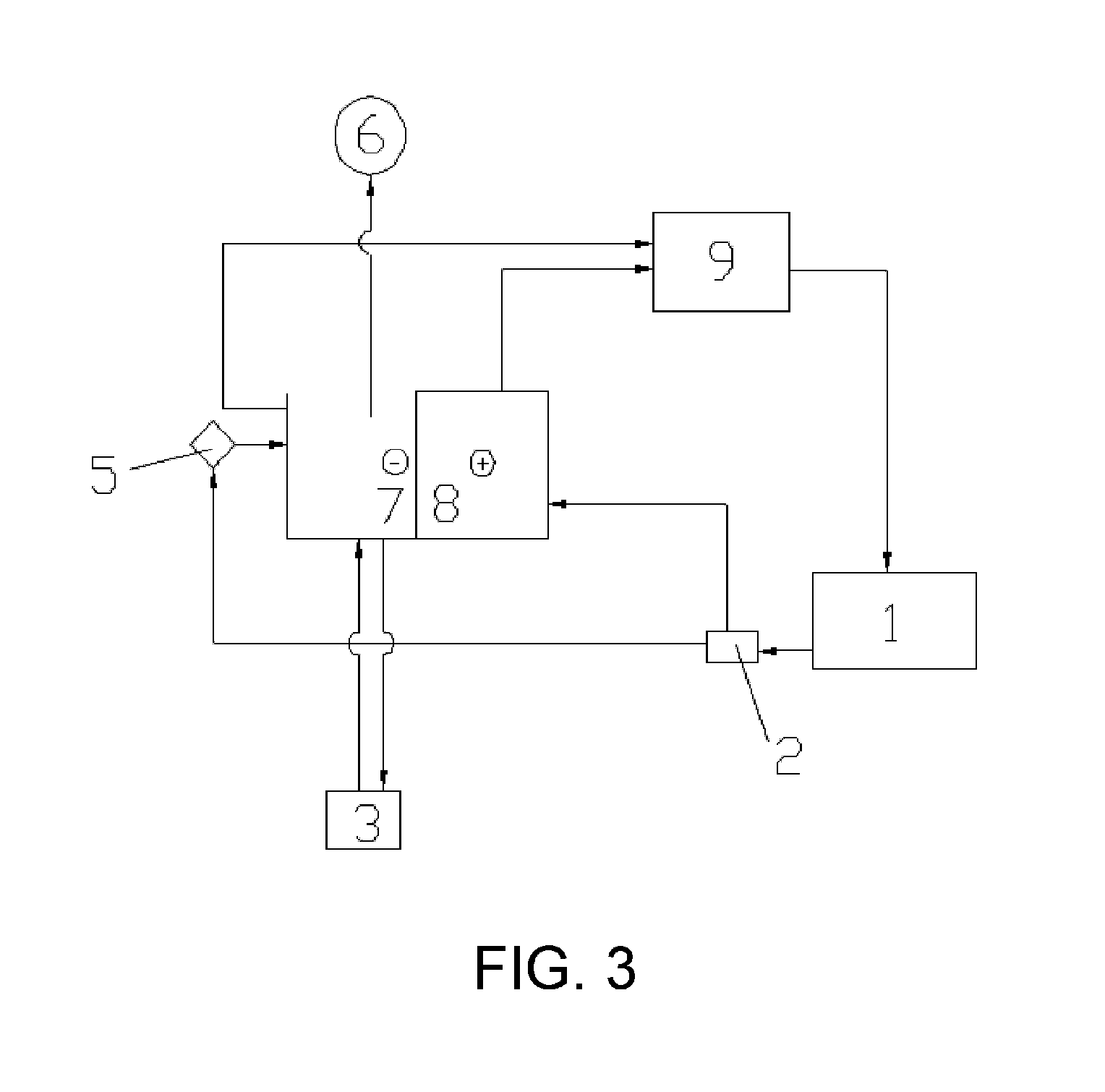
[0090]The electrolytic recycling and regenerating apparatus employed in this embodiment is illustrated in FIG. 3.

(1) In combination with the method above, according to the designated components and their mixing ratios as shown in Table 1 and 2 below, the etchant was prepared and the automatic detection and charging control machine was set up, and the etching operated was started. The aqueous oxidant mixture used in the embodiment was comprised of 15 wt % of NaClO3, 20 wt % of NH4Cl, and 65 wt % of water.

(2) The etchant waste overflowed from etchant tank 1 was collected and treated by water-oil separator 2; the etchant waste contained products of copper-etching, such as ferrous chloride and cuprous chloride.

(3) The treated etchant waste was introduced to an electrolysis tank with a built-in electrolytic diaphragm. One part of the etchant waste was directly transferred to anode chamber 8, and the other part of the etchant waste was mixed with hydrochloric acid, ferric chloride and wat...


PUM

PropertyMeasurementUnit
Fractionaaaaaaaaaa
Fractionaaaaaaaaaa
Fractionaaaaaaaaaa

Abstract

A method for electrolytic recycling and regenerating acidic cupric chloride etchants, comprising: (1) employing an acidic cupric chloride etchant that contains iron ions in PCB etching, controlling the oxidation-reduction potential (ORP) of said acidic cupric chloride etchant within the range of 360-700 mV; (2) transferring an etchant waste of step (1) to an electrolysis tank and electrolysing said etchant waste; (3) the chlorine gas generated by electrolysis oxidizes the electrolyte in the electrolysis tank and thereby dissolved into the electrolyte, in the effect of the ORP of the electrolyte; (4) regenerating an etchant by oxidizing Fe(II) ions and Cu(I) ions in the electrolyte to Fe(III) ions and Cu(II) ions using the chlorine gas of step (3) that is dissolved into the electrolyte, and when the chlorine gas is fully dissolved into the electrolyte, the oxidizing step of the electrolyte is finished and an etchant is regenerated; (5) transferring the etchant regenerated in step (4) to an etching production line.

Description

FIELD OF INVENTION[0001]The present invention relates to the recycling and regeneration of printed circuit board etchants, particularly relates to a method for electrolytic recycling and regenerating acidic cupric chloride etchants.TECHNICAL BACKGROUND[0002]In the etching of printed circuit boards (PCBs), an etchant is continuously sprayed onto pre-developed copper-clad laminates, etching away the unprotected copper to form circuits. It has been a common practice to use either acidic cupric chloride or ferric chloride etching method for copper etching. The acidic cupric chloride etching method relies on the use of an acidic cupric chloride etchant, the main components of which are: (1) cupric chloride, the main copper-etching agent, (2) an oxidant and (3) a sub-etchant that mainly contains hydrochloric acid. The composition of the etchant changes continuously as it reacts with copper-clad laminates during etching, therefore an automatic detection and charging control machine is wide...

Claims


Application Information

Patent Timeline
IPC IPC(8): C25B1/26C25B15/08H05K3/00C25B1/22
CPCC25B1/26H05K3/002C25B15/08C25B1/22C23F1/18C23F1/46C25C1/12H05K3/067Y02P10/20
Inventor YE, YITING
Owner YE YITING
Why Eureka
Try Eureka