Flyback diode and on-board power source device
a power source device and flyback diode technology, applied in the direction of solid-state devices, dc-ac conversion without reversal, semiconductor/solid-state device details, etc., can solve the problem of em not progressing the yield of sicsbd is decreased, and the em does not progress in the solder layer bonding process, etc. problem, to achieve the effect of reducing the loss, reducing the loss, and reducing the loss ra
- Summary
- Abstract
- Description
- Claims
- Application Information
AI Technical Summary
Benefits of technology
Problems solved by technology
Method used
Image
Examples
first embodiment
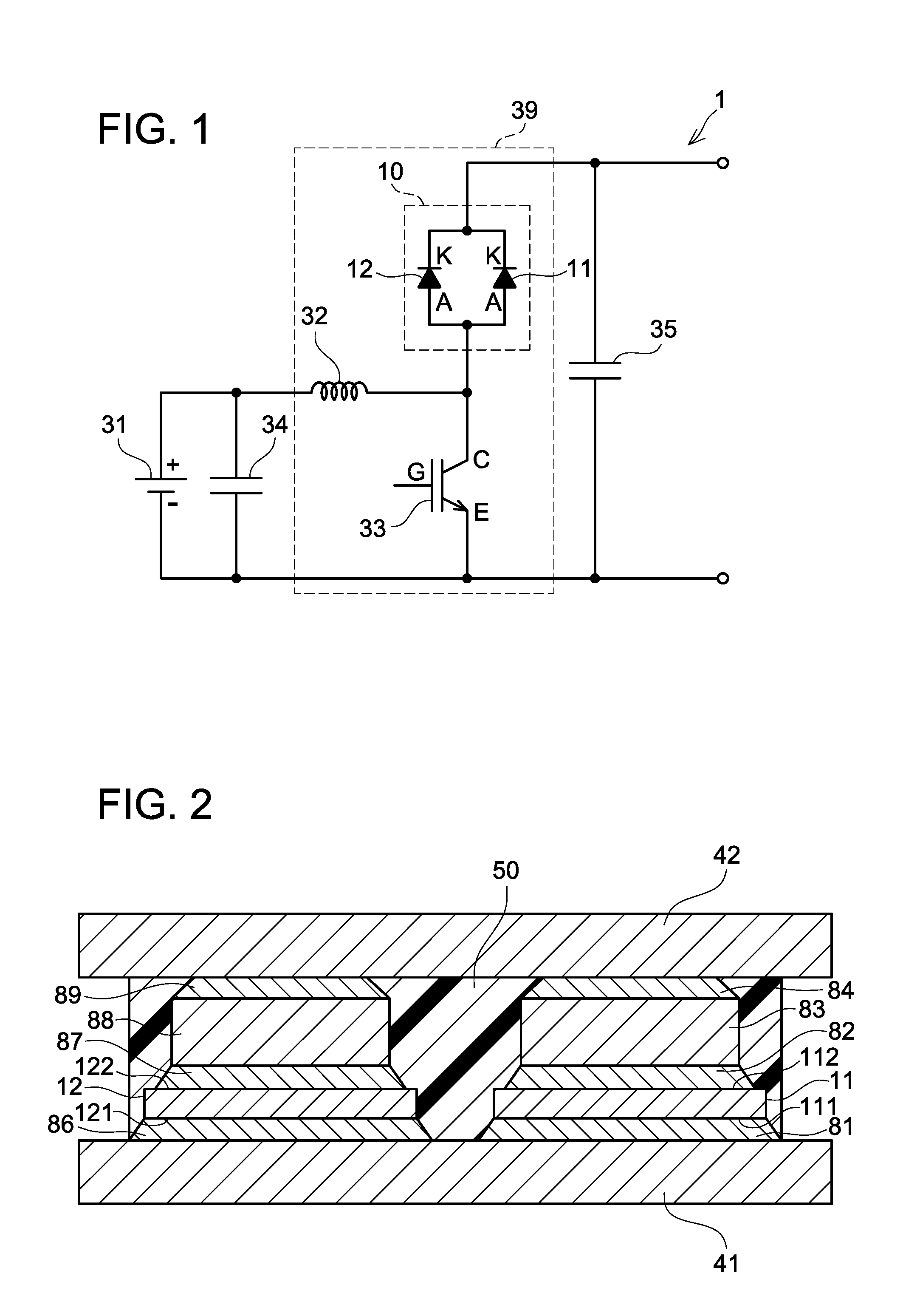
[0033]As shown in FIG. 1, an on-board power source device 1 of a first embodiment comprises a battery 31, a first capacitor 34, a converter 39, and a second capacitor 35. Power supplied from the battery 31 is output via the converter 39. The converter 39 boosts a voltage of the battery 31. The battery 31 is configured capable of recharging and discharging. This on-board power source device 1 is mounted for example on an electric vehicle, a hybrid vehicle, or a fuel cell vehicle and supplies power to a traction motor.
[0034]The converter 39 comprises a coil 32, a flyback diode 10 on an upper arm thereof, and a switching element 33 on a lower arm thereof. In the present embodiment, an IGBT (Insulated Gate Bipolar Transistor) is used as the switching element 33.
[0035]The flyback diode 10 comprises a Schottky-barrier diode (SiCSBD) 11 provided with a SiC substrate and a PiN diode (SiPiND) 12 provided with a Si substrate. The SiCSBD 11 and the SiPiND 12 are connected in parallel. The SiCS...
second embodiment
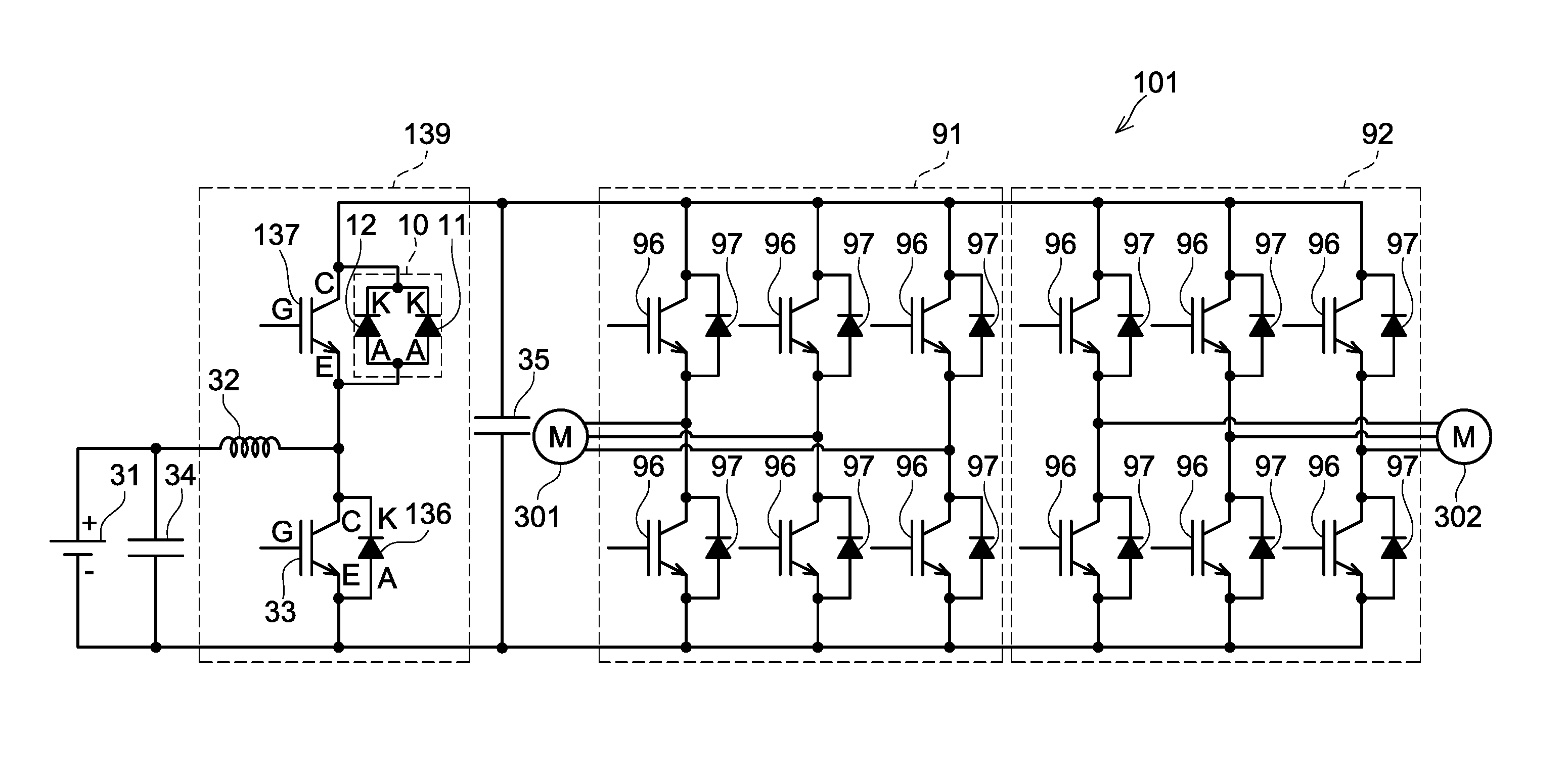
[0055]As shown in FIG. 4, an on-board power source device 101 of a second embodiment comprises a battery 31, a first capacitor 34, a converter 139, a second capacitor 35, a first inverter 91, and a second inverter 92. Power supplied from the battery 31 is input to the first inverter 91 and the second inverter 92 via the converter 139. The converter 139 boosts the battery 31.
[0056]The converter 139 comprises a coil 32, a first switching element 33, a flyback diode 136, a second switching element 137, and a flyback diode 10. In the present embodiment, a PiN diode provided with a Si substrate is used as the lower-arm flyback diode 136. Further, in the present embodiment, an IGBT is used as the upper-arm second switching element 137. Notably, the first switching element 33 has the same configuration as the switching element 33 of the above first embodiment.
[0057]The first switching element 33 and the flyback diode 136 are connected in anti-parallel. A cathode electrode of the flyback di...
example
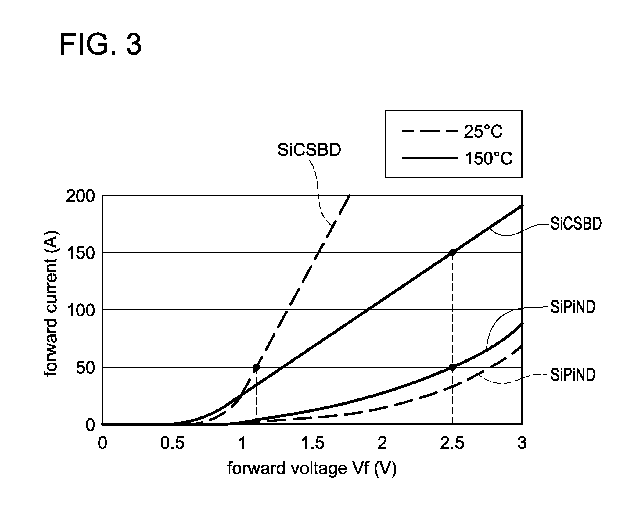
[0066]Next, one method of determining an area of the SiCSBD 11 and an area of the SiPiND 12 will be described. Firstly, a maximum rated current density by which the solder layers in the SiCSBD 11 can be used without a problem will be assumed as F (Amp / cm2 =A / cm2). The maximum rated current density F can be obtained experimentally. For example, the maximum rated current density can be determined by considering a detaching rate of the solder layer 84, in which the EM is most likely to occur when a current flows in the SiCSBD 11. Further, the area of the SiCSBD 11 (area of an active region of the SiCSBD 11) will be assumed as E (cm2). In this case, a maximum current A (A) that flows in the SiCSBD 11 becomes A=F×E (A). Further, the forward voltage when the current A (A) flows in the SiCSBD 11 will be assumed as Vf1 (V).
[0067]On the other hand, a maximum rated current of the flyback diode 10 will be assumed as A+B (A). In this case, a current desired to flow in the SiPiND 12 of the flyba...
PUM
 Abstract
Description
Claims
Application Information
 - R&D
- Intellectual Property
- Life Sciences
- Materials
- Tech Scout
- Unparalleled Data Quality
- Higher Quality Content
- 60% Fewer Hallucinations
Browse by: Latest US Patents, China's latest patents, Technical Efficacy Thesaurus, Application Domain, Technology Topic, Popular Technical Reports.
© 2025 PatSnap. All rights reserved.Legal|Privacy policy|Modern Slavery Act Transparency Statement|Sitemap|About US| Contact US: help@patsnap.com


