Microfluidic capture and detection of biological analytes

a biological analyte and microfluidic technology, applied in the field of microfluidic capture and detection of biological analytes, can solve the problems of high hiv viral load, laborious and time-consuming viral load testing, and inability to detect high-risk bacteria, so as to improve detection accuracy, improve detection accuracy, and improve detection accuracy

Inactive Publication Date: 2017-03-30
CYCLIC SOLUTIONS LLC
View PDF12 Cites 3 Cited by
  • Summary
  • Abstract
  • Description
  • Claims
  • Application Information

AI Technical Summary

Benefits of technology

[0007]The device of the present invention is easier to operate, has a faster turnaround time, and is less expensive than nucleic acid amplification-based tests. This lab-on-a-chip design utilizes microfluidics for capture and quantification of whole HIV virions. The small size of microflu

Problems solved by technology

A high HIV viral load may indicate treatment failure, i.e. that the virus is replicating and the disease may progress more quickly.
Although useful, viral load testing can be labor intensive, expensive and time consuming.
It often takes upwards of two weeks to receive a patient's viral load results from centra

Method used


Image

  • Microfluidic capture and detection of biological analytes
  • Microfluidic capture and detection of biological analytes
  • Microfluidic capture and detection of biological analytes

Examples


example

Example 1—Method of Fabricating the Regular Macroporous Layer

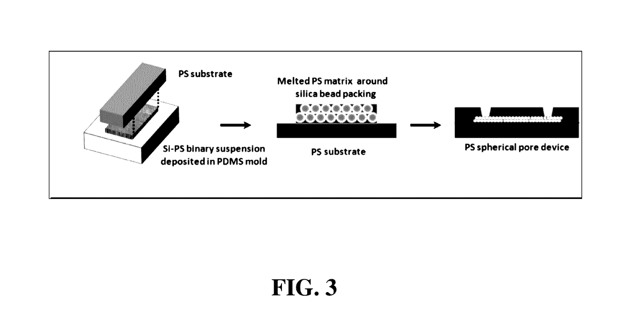
[0073]A methods of fabricating the regular macroporous layer is described. The polystyrene (PS) spherical pore devices were fabricated by templating close-packed silica beads. First, a polydimethyl siloxane (PDMS) open channel of 25 mm×8 mm×30 μm was fabricated using standard soft lithography. The PDMS surface was pretreated by a plasma gun to promote spreading of the suspension throughout the open channel. Then, 20 μL of a binary suspension of 1-μm silica and 100-nm PS in de-ionized water was pipetted into the PDMS channel. After drying, the silica beads self-assembled into ordered structures with the PS beads filling the interstitial space. Next, the PS nanobeads were melted at 240° C. for 10 min. The sample was glued to a PS flat sheet by epoxy glue and the PDMS mold was peeled off. Afterwards, silica beads were removed in 50% hydrofluoric acid and the device was rinsed in DI water. The porous matrix was attached to a f...

example ii

or Fabrication a Microfluidic Capture Device

[0074]The steps of the protocol for fabricating a microfluidic capture device according to the present invention are described below, in numeric order.

[0075]i. A binary suspension is composed of 20% silica (SiO2, diameter=1 μm) and 8% polystyrene (PS, diameter=0.2 μm).

[0076]ii. Using standard soft photolithography, a positive mold with dimensions 25 mm×8 mm×30 μm SU-8 photoresist is spun onto a silicon wafer.

[0077]iii. Poly(dimethyl siloxane) (PDMS) is poured over the mold and cured for two hours at 60° Celsius.

[0078]iv. The PDMS is cut in a rectangular shape enclosing the area of the mold.

[0079]v. The PDMS is placed on a glass slide with the negative mold facing up.

[0080]vi. The area of the negative mold is plasma oxidized for ten seconds.

[0081]vii. 20 μL of the binary suspension is deposited to fill the mold and spread evenly.

[0082]viii. After 30 minutes, the glass slide with PDMS and binary suspension is heated at 240° Celsius for 10 mi...

example 3

ssay for Aggregate Building

[0094]i. Steps in binding assay may be run under flow or static conditions and have been optimized for greatest viral capture and aggregate formation when used to quantify HIV. Times may be further optimized in the future to increase signal or validate capture with other analytes.

[0095]ii. The device is functionalized with 100 μL of 10 μg / mL neutravidin (or other antibody or molecule capable of capturing a biomolecule of interest such as anti-gp120) at a flow rate of 5 μL / min or injected statically for 20 min. A static incubation at 4° Celsius for at least 2 hours can be used.

[0096]iii. 200 μL of solution containing the biomolecule of interest (e.g., HIV particles) is flowed through device at a rate of 15 μL / min under flow or injected statically for 8 minutes. Alternately, 250 uL of solution containing the biomolecule of interest (e.g., HIV) is flowed through device at a rate of 15 μL / min under flow or injected statically for 17 minutes.

[0097]iv. 100 μL of...


PUM


Abstract

A microfluidic capture device is described that include a regular macroporous layer comprising a binding molecule, an inlet and outlet port fluidly connected to the regular macroporous layer and configured to add or remove a biological sample to the regular macroporous layer and positioned to allow flow of the biological sample through a flow region in the regular macroporous layer, a first and second electrode positioned on opposite sides of the flow region, and a substrate enclosing the regular macroporous layer, including top and bottom sides on opposite sides of the regular macroporous layer. Methods of using the device to qualitatively and/or quantitatively determine the amount of a biological analyte such as a virus particle in a biological sample obtained from a subject using cyclic voltammetry are also described.

Description

CONTINUING APPLICATION DATA[0001]This application claims the benefit of U.S. Provisional Application Ser. No. 62 / 234,017, filed Sep. 28, 2015, the disclosure of which is incorporated by reference herein.TECHNICAL FIELD[0002]This disclosure relates to systems and methods for detecting and quantifying biological material within a sample, and more particularly to systems and methods for quantitative viral sensing, including quantitative viral sensing employing electrochemical cyclic voltammetry.BACKGROUND[0003]Viruses and other biological material and analytes are often blood borne. The amount of the analyte in the blood can indicate the presence of a disease, as well as the success of treatment and / or staging of the disease.[0004]Testing of the quantity of a virus within a patient's blood is a useful proxy for the severity of the viral infection. The amount of the virus, that is the concentration of virus circulating in the blood, often referred to as the viral load, can be used to mo...

Claims


Application Information

Patent Timeline
IPC IPC(8): G01N33/569G01N27/327G01N27/416B01L3/00
CPCG01N33/56988B01L3/502715B01L3/502761G01N27/3277G01N2333/16B01L2300/12B01L2300/0887B01L2300/0645B01L2200/0647G01N27/416G01N33/5438B01L3/502753
Inventor KUNDROD, KATHRYNFRASER, JOHN
Owner CYCLIC SOLUTIONS LLC
Why Eureka
Try Eureka