Porous coatings

a technology of porous coatings and coating compositions, applied in the direction of sustainable manufacturing/processing, mechanical equipment, lighting and heating apparatus, etc., can solve the problems of conventional porous coatings suffering from an unacceptably high t, 960, inefficiency of porous coatings,

Active Publication Date: 2017-04-20
PRAXAIR TECH INC
View PDF9 Cites 21 Cited by
  • Summary
  • Abstract
  • Description
  • Claims
  • Application Information

AI Technical Summary

Benefits of technology

[0009]In a first aspect of the present invention, a porous coating applied onto a substrate is provided comprising: metallic particles comprising aluminum, magnesium and tin, wherein the aggregate amount of magnesium and tin is not greater than 15 wt %, based on the weight of the porous coating, and the balance is alu

Problems solved by technology

However, currently available porous coatings, such as those mentioned in U.S. Pat. No. 4,917,960, are inefficient, particularly for cryogenic boiling heat transfer applications.
Generally speaking, conventional porous coatings suffer from an unacceptably high ΔT.
In other words, a large amount of heat energy is required to be transferred to the boiling surface to boil the process fluid, which translates into inefficient processes having excessive power consumption.
These conventional porous coatings d

Method used


Image

  • Porous coatings
  • Porous coatings
  • Porous coatings

Examples


example 1

611-S11-Z

[0045]Coating 611-S 11-Z was prepared from a slurry having the following constituents: 66 wt % aluminum powder (commercially available as Ampal® 611); 0.67 wt % Mg; 0.34 wt % Sn; 2 wt % PVB; and 30 wt % IPA solvent. The median particle size was approximately 43 μm. The slurry constituents were thoroughly mixed. The slurry was then applied onto the substrate by dip coating.

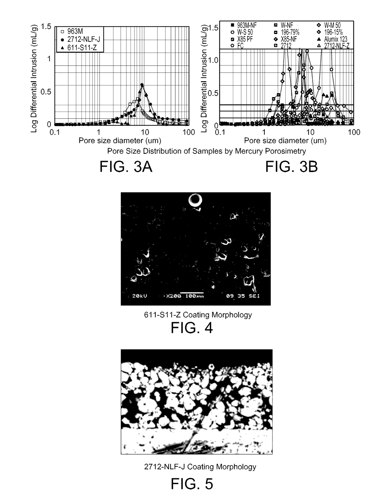
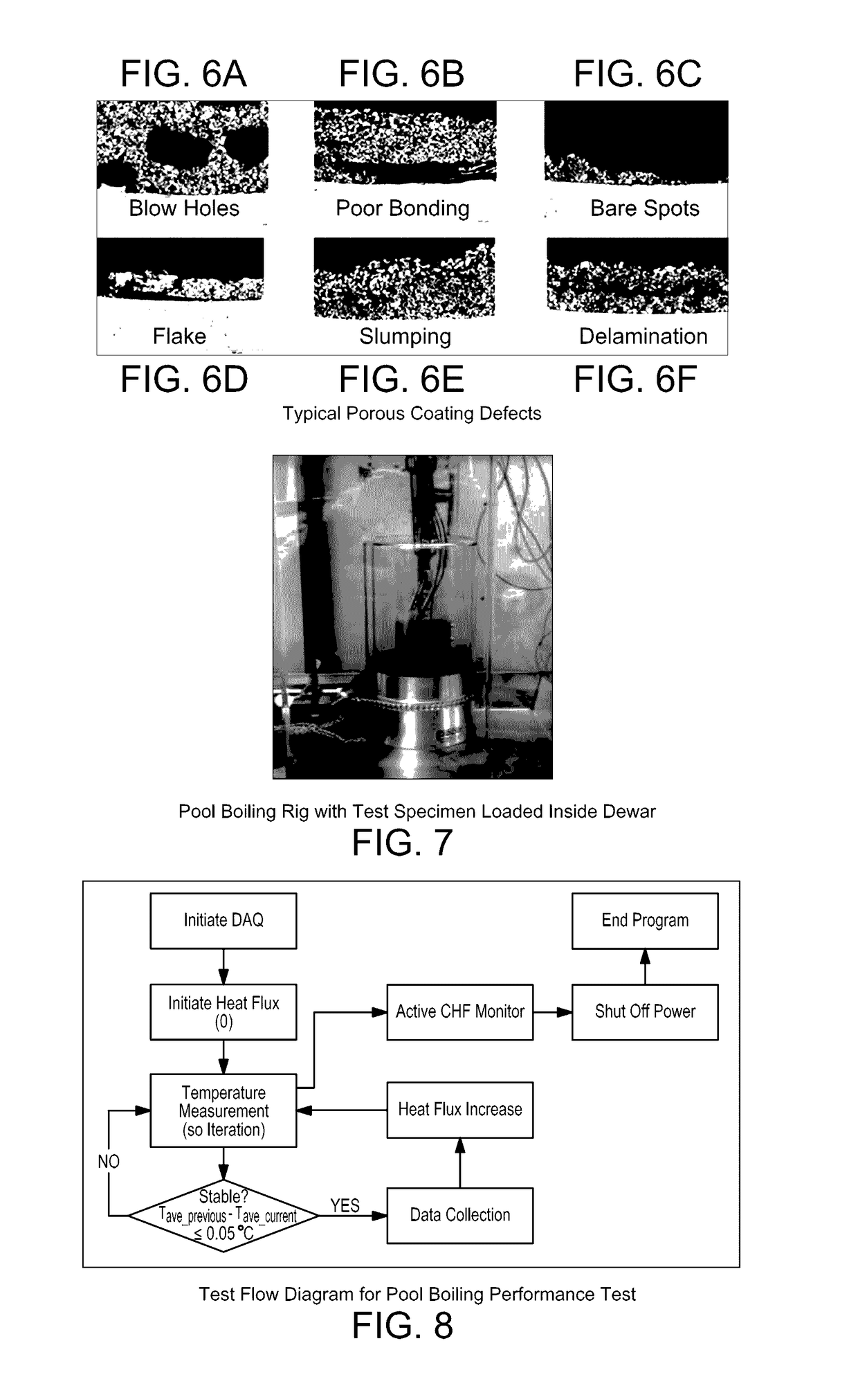
[0046]A drying process for IPA solvent evaporation was performed at ambient temperature for about 30 minutes. Next, the binder PVB was burned by heating the coating in a furnace at 450° C. for 1 hour in air, followed by sintering at 580° C. for 1 hour in nitrogen. The microstructure was visually observed SEM as shown in FIG. 4. SEM as shown in FIG. 4. The resultant coating morphology is shown in FIG. 4. No coating defects as shown in FIG. 6a, 6b, 6c, 6d, or 6e were observed. The median pore size was about 10 μm and the pore size distribution was determined to be normally distributed as shown in FIG. 3a.

example 2

611-S11-Z Coating Performance

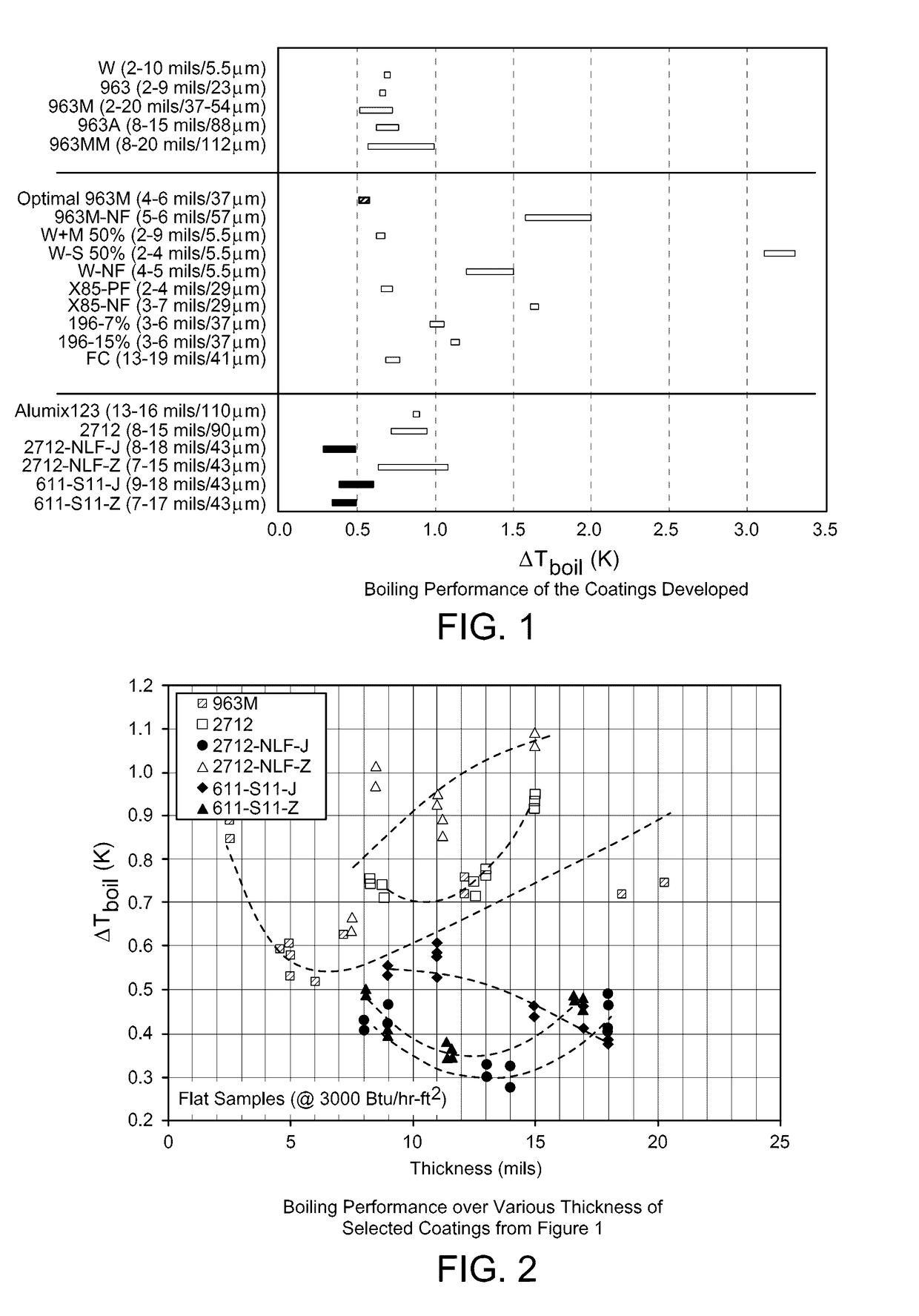
[0047]The porous coating of Example 1 was evaluated for performance by conducting the pool boiling experiment as described above. The test heater assembly (Table 1) was prepared with the porous coating of Example 1. The heater assembly was then loaded inside a dewar as shown in FIG. 7. The pool boiling experiment was initiated as shown in FIG. 8. The boiling ΔT was obtained at a heat flux of 3000 Btu / hr-ft2. The results for 611-S11-Z are shown in FIG. 1.

[0048]Additional boiling experiment tests using 611-S11-Z were conducted to evaluate the effects of coating thickness. The results are shown in FIG. 2. 611-S11-Z displayed the best results at a coating thickness of about 330 μm. 611-S11-Z outperformed the other screened coatings at all thicknesses.

example 3

2712-NLF-J

[0049]Coating 2712-NLF-J was prepared from a slurry having the following constituents: 55 wt % commercially available Ampal® 2712 aluminum alloy powder containing 0.8-1.2 wt % Mg; 3.6-4.0 wt % Cu; 0.6-0.9 wt % Si; 44 wt % ethanol; 0.27 wt % hydroxypropyl cellulose; and 1-2 drops of a defoaming agent (commercially available as MD-20). The median particle size was approximately 43 μm. The slurry constituents were thoroughly mixed. The slurry was then applied onto the substrate by dip coating.

[0050]Drying process for solvent evaporation was performed at ambient temperature for about 30 minutes. Next, the binder was burned by heating the coating in a furnace at 450° C. for 1 hour in air, followed by sintering at 620° C. for 1 hour in nitrogen. The microstructure was visually observed by SEM as shown in FIG. 5. The resultant coating morphology is shown in FIG. 5. No coating defects as shown in FIG. 6a, 6b, 6c, 6d, 6e or 6f were observed. The median pore size was about 10 μm and...


PUM

PropertyMeasurementUnit
Diameteraaaaaaaaaa
Lengthaaaaaaaaaa
Lengthaaaaaaaaaa

Abstract

A porous metallic coating is provided. The coating is characterized by a combination of optimized properties that improve coating performance, as measured by heat transfer efficiency. The porous coating has optimal ranges for properties such as porosity, particle size and thickness, and has particular applicability in boiling heat transfer applications as part of an air separations unit. The porous coatings are derived from slurry-based formulations that include a mixture of metallic particles, a binder and a solvent.

Description

FIELD OF THE INVENTION[0001]This invention relates to novel slurry and metallic porous coating compositions along various surfaces to enhance heat transfer. More particularly, the coating compositions optimized to improve the performance of various cryogenic boiling applications.BACKGROUND OF THE INVENTION[0002]Heat exchangers are utilized in a variety of industrial processes to transfer heat between two or more fluids by indirect heat exchange. There are different designs for heat exchangers. For instance, one heat exchanger design is commonly referred to as a shell and tube design in which one fluid flows through the tubes and another fluid flows outside the tubes but inside a shell housing that retains the tubes. The fluid can be a liquid, vapor or a combination thereof. Further, the shell can be formed by or integrated with other equipment in which the heat transfer is to be conducted, such as, for example, a distillation column.[0003]In another type of design, known as a plate-...

Claims


Application Information

Patent Timeline
IPC IPC(8): F16L9/02C09D131/02C09D101/28C08J9/00
CPCF16L9/02C08J9/0066C08J2301/28C09D101/284C08J2331/02C09D131/02B22F7/002B22F7/004C09D5/26C09D1/00C09D5/00C23C24/082C08K3/08F28F13/187C08K2003/0812C08K2201/003C08K2201/014Y02P20/10C08K3/22
Inventor LU, ZIGUIKWARK, SANG MUKCORPUS, JOSEPH M.LANE, JONATHAN A.POTEMPA, DAVID P.SHELAT, MAULIK R.
Owner PRAXAIR TECH INC
Why Eureka
Try Eureka