
Electrochemical device and its manufacturing method

a technology of electrochemical devices and manufacturing methods, applied in the direction of cell components, final product manufacturing, sustainable manufacturing/processing, etc., can solve the problems of lithium-ion polymer batteries with a relatively lower battery capacity, lithium-ion polymer batteries have a relatively low battery capacity, and the disadvantages of lithium-ion polymer batteries are still to be solved urgently, so as to achieve excellent thermal stability and good economic efficiency

Active Publication Date: 2010-01-07
LG ENERGY SOLUTION LTD
View PDF13 Cites 50 Cited by
  • Summary
  • Abstract
  • Description
  • Claims
  • Application Information

AI Technical Summary

Benefits of technology

[0007]An object of the present invention is to provide an electrochemical device having excellent thermal stability and good economical efficiency by adopting a porous coating layer to a porous substrate.
[0008]Another object of the present invention is to provide a method for manufacturing an electrochemical device with excellent thermal stability in a simple and economical way.Technical Solution

Problems solved by technology

However, such a lithium secondary battery has disadvantages in that organic electrolytes used therein may cause safety-related problems such as ignition and explosion of the batteries and that processes for manufacturing such a battery are complicated.
However, the lithium-ion polymer batteries have a relatively lower battery capacity than those of the lithium ion batteries and an insufficient discharging capacity in low temperature, and therefore these disadvantages of the lithium-ion polymer batteries remain to be urgently solved.
In the stability characteristics of the electrochemical device, overheating of the electrochemical device may cause thermal runaway, and explosion may occur when a separator is pierced.
In particular, a polyolefin porous substrate commonly used as a separator of an electrochemical device shows extreme thermal shrinking behavior at a temperature of 100 C or above due to the features of its material and its manufacturing process such as elongation, so there may occur an electric short circuit between cathode and anode.

Method used


Image

  • Electrochemical device and its manufacturing method
  • Electrochemical device and its manufacturing method

Examples


example 1

EXAMPLE 1

Manufacture of Composite Separator

[0055]PVdF-CTFE (polyvinylidene fluoride-co-chlorotrifluoroethylene) and cyanoethylpullulan were respectively added to acetone at a weight ratio of 10:2 and then dissolved at 50° C. for about 12 hours to make a polymer solution. Cathode active material powder (LiCoO2) and conductive material were added to the prepared polymer solution such that a weight ratio of polymer mixture / cathode active material powder / conductive material is 6 / 90 / 4, and then activated carbon powder was pulverized and dispersed for over 12 hours by means of ball milling to make a slurry. The cathode active material particles of the prepared slurry may be controlled according to size (diameter) of beads used for ball milling or time for ball milling, but this example conducted pulverization into about 600 nm to make the slurry.

[0056]The prepared slurry was applied to one surface of a polyethylene porous separator (having a porosity of 45%) with a thickness of 12 μm by ...

example 2

Manufacture of Composite Separator

[0060]PVdF-CTFE (polyvinylidene fluoride-co-chlorotrifluoroethylene) and cyanoethylpullulan were respectively added to acetone at a weight ratio of 10:2 and then dissolved at 50° C. for about 12 hours to make a polymer solution. Cathode active material powder (LiCoO2) and conductive material were added to the prepared polymer solution such that a weight ratio of polymer mixture / cathode active material powder / conductive material is 6 / 90 / 4, and then activated carbon powder was pulverized and dispersed for over 12 hours by means of ball milling to make a slurry. The cathode active material particles of the prepared slurry had a diameter of about 600 nm.

[0061]The prepared slurry was applied to one surface of a polyethylene porous separator (having a porosity of 45%) with a thickness of 12 μm by means of roll coating to form a porous coating layer. The coating thickness was controlled to be about 100 μm. A pore size in the porous coating layer formed on ...

example 3

Manufacture of Composite Separator

[0063]PVdF-CTFE (polyvinylidene fluoride-co-chlorotrifluoroethylene) and cyanoethylpullulan were respectively added to acetone at a weight ratio of 10:2 and then dissolved at 50° C. for about 12 hours to make a polymer solution. Graphite anode active material powder was added to the prepared polymer solution such that a weight ratio of polymer mixture / graphite powder / conductive material is 6 / 93 / 1, and then the graphite powder was pulverized into about 800 nm and dispersed for over 12 hours by means of ball milling to make a slurry. The prepared slurry was applied to the other surface of the polyethylene porous separator by means of roll coating and then dried to form a porous coating layer. The coating thickness was controlled to be about 50 μm.

Manufacture of Battery

[0064]The composite separator prepared as above was interposed between a copper (Cu) film with a thickness of 10 μm and a cathode active material LiCoO2 such that the porous coating laye...


PUM

PropertyMeasurementUnit
Thicknessaaaaaaaaaa
Sizeaaaaaaaaaa
Weight ratioaaaaaaaaaa

Abstract

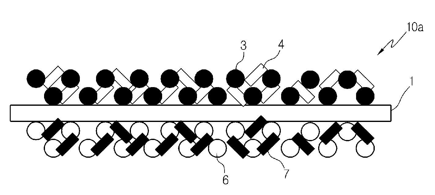
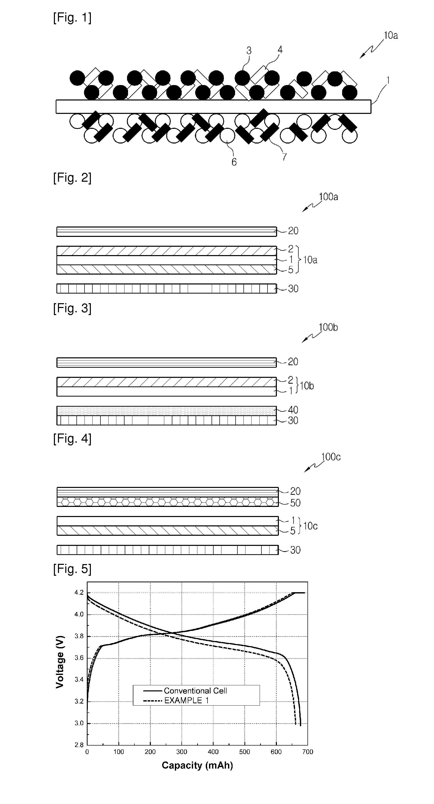
An electrochemical includes an electrode structure provided with a composite separator having a porous substrate with a plurality of pores and a porous coating layer formed on at least one surface of the porous substrate and made of a mixture of electrode active material particles and a binder polymer. The porous coating layer of the composite separator improves thermal stability of the porous substrate and plays a function of electrode active material layer of the electrochemical device. Accordingly, this electrochemical device has excellent stability and good economical efficiency since the electrode structure does not need coating of an electrode active material layer on a surface of a current collector.

Description

TECHNICAL FIELD[0001]The present invention relates to an electrochemical device and its manufacturing method, and more particularly to an electrochemical device to which an electrode structure having a composite separator in which a porous coating layer is formed with a mixture of filler particles and binder polymer onto a surface of a porous substrate is applied.BACKGROUND ART[0002]Recently, there has been an increasing interest in energy storage technology. Batteries have been widely used as energy sources in the fields of cellular phones, camcorders, notebook computers, PCs and electric cars, resulting in intensive research and development into them. In this regard, electrochemical devices are one of the subjects of great interest. Particularly, development of rechargeable secondary batteries has been the focus of attention. Recently, the research and development into a novel electrode and a novel battery that can improve capacity density and specific energy have been made intens...

Claims


Application Information

Patent Timeline
IPC IPC(8): H01M2/18H01M10/04H01M4/02H01M4/131H01M4/133H01M4/134H01M50/414H01M50/457H01M50/489
CPCH01M2/1673H01M4/131H01M4/133Y10T29/49112H01M4/623H01M2/1653H01M4/622H01M4/134Y02E60/10H01M50/46Y02P70/50H01M50/457H01M50/414H01M50/489H01M4/661H01M10/058H01M10/052H01M4/136H01M2004/021H01M50/446H01M50/403H01M4/621H01M50/461
Inventor PARK, PIL-KYULEE, SANG-YOUNG
Owner LG ENERGY SOLUTION LTD
Learn More