Separator including porous coating layer, method for manufacturing the separator and electrochemical device including the separator

Active Publication Date: 2012-01-19
LG ENERGY SOLUTION LTD +1
View PDF4 Cites 51 Cited by
  • Summary
  • Abstract
  • Description
  • Claims
  • Application Information

AI Technical Summary

Benefits of technology

[0016]The separator of the present invention has a structure in which a porous coating layer is formed on a non-woven fabric substrate whose large pores are filled with fine thermoplastic powder. Due to this structure, the separator of the present invention exhibits the following advantageous effects.
[0017]First, previous filling of large pores of the non-woven fabric with the fine thermoplastic powder makes the porous coating layer uniform and maintains the uniformity of the porous coating layer even when the separator is pressurized in the fabrication process of a battery. Therefore, the occurrence of charging failure and leak

Problems solved by technology

However, such lithium ion batteries suffer from safety problems, such as fire or explosion, when encountered with the use of organic electrolytes and are disadvantageously complicated to fabricate.
Overheating of an electrochemical device may cause thermal runaway or a puncture of a separator may pose an increased risk of explosion.
This thermal shrinkage behavior may cause short circuits between a cathode and an anode.
When such a separator including a porous coating layer

Method used


Image

  • Separator including porous coating layer, method for manufacturing the separator and electrochemical device including the separator
  • Separator including porous coating layer, method for manufacturing the separator and electrochemical device including the separator

Examples


example 1

Manufacture of Separator

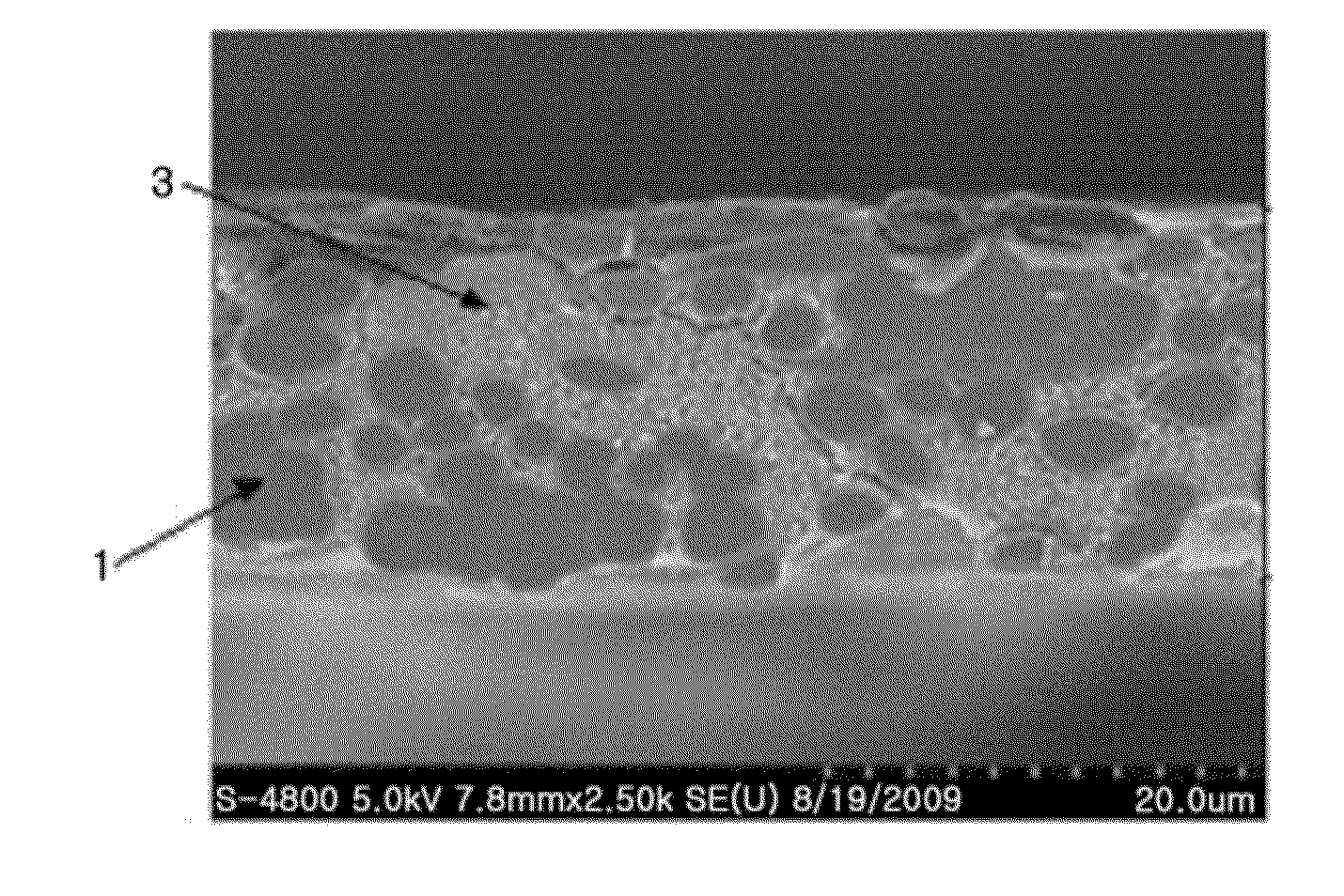
[0058]About 14 μm thick of non-woven fabric was prepared. The non-woven fabric was composed of polyethylene terephthalate microfibers having an average thickness of about 10 μm. The pores of the non-woven fabric had an average diameter of 7 μm and a longest diameter distribution of 1 to 20 μm.

[0059]60 wt % of powder (average diameter=0.3 μm) of polyvinylidene fluoride as a thermoplastic polymer was dispersed in water. The non-woven fabric was dipped in and taken out of the aqueous dispersion. The wet non-woven fabric was dried with hot air to remove the water. FIG. 1 is a cross-sectional scanning electron microscope (SEM) image of the resulting substrate. Referring to FIG. 1, the pores of the non-woven fabric substrate 1 were filled with the fine thermoplastic powder 3.

[0060]Meanwhile, polyvinylidene fluoride-co-hexafluoropropylene and cyanoethyl polyvinyl alcohol were added in a weight ratio of 10:2 to acetone. The mixture was dissolved at 50° C. for at leas...

example 2

[0067]A separator was manufactured in the same manner as in Example 1, except that powder (average diameter=0.5 μm) of polystyrene as a thermoplastic polymer was used instead of the polyvinylidene fluoride powder. Thereafter, the procedure of Example 1 was repeated to fabricate a prismatic battery and a cylindrical battery.

example 3

[0068]A separator was manufactured in the same manner as in Example 1, except that powder (average diameter=3 μm) of polyethylene as a thermoplastic polymer was used instead of the polyvinylidene fluoride powder. Thereafter, the procedure of Example 1 was repeated to fabricate a prismatic battery and a cylindrical battery.


PUM


Abstract

A separator includes a non-woven fabric substrate having pores, fine thermoplastic powder located inside the pores of the non-woven fabric substrate, and a porous coating layer disposed on at least one surface of the non-woven fabric substrate. The fine thermoplastic powder has an average diameter smaller than that of the pores and a melting point lower than the melting or decomposition point of the non-woven fabric substrate. The porous coating layer includes a mixture of inorganic particles and a binder polymer whose melting point is higher than the melting or decomposition point of the fine thermoplastic powder. In the porous coating layer, the inorganic particles are fixedly connected to each other by the binder polymer and the pores are formed by interstitial volumes between the inorganic particles. Previous filling of the large pores of the non-woven fabric substrate with the fine thermoplastic powder makes the porous coating layer uniform.

Description

CROSS-REFERENCE TO RELATED APPLICATION[0001]This application is a continuation of International Application No. PCT / KR2010 / 002106 filed on Apr. 6, 2010, which claims priority under 35 USC 119(a) to Korean Patent Application Nos. 10-2009-0031234 and 10-2010-0030996 filed in the Republic of Korea on Apr. 10, 2009 and Apr. 5, 2010, respectively, the entire contents of which are incorporated herein by reference.TECHNICAL FIELD[0002]The present invention relates to a separator for an electrochemical device such as a lithium secondary battery, a method for manufacturing the separator, and an electrochemical device including the separator. More specifically, the present invention relates to a separator in which a porous coating layer composed of a mixture of inorganic particles and at least one binder polymer is formed on at least one surface of a non-woven fabric substrate, a method for manufacturing the separator, and an electrochemical device including the separator.BACKGROUND ART[0003]...

Claims


Application Information

Patent Timeline
IPC IPC(8): H01M2/16B05D1/36B05D5/00B05D3/00H01M2/18B05D7/00H01M50/403H01M50/414H01M50/417H01M50/426H01M50/434H01M50/451
CPCH01M2/162H01M2/1653Y02E60/122H01M2/1666H01M10/052H01M2/166Y02E60/10H01M50/44H01M50/446H01M50/417H01M50/403H01M50/451H01M50/414H01M50/434H01M50/426H01M50/491H01M50/454H01M50/443H01M50/431H01M10/0525C08J9/22Y02P70/50
Inventor YOON, SU-JINPARK, PIL-KYUKIM, JONG-HUNYOO, JIN-NYOUNGKIM, IN-CHULLEE, SANG-YOUNG
Owner LG ENERGY SOLUTION LTD
Why Eureka
Try Eureka