Sensor, telemeter, wireless sensor system and use method thereof

a wireless sensor and sensor technology, applied in the field of sensor systems, can solve the problems of address and sensitive variable not being determined, address code needs to be realized in lithography process, and inability to integrate multiple access functions without external power supply, etc., to achieve the effect of expanding the scope of communication and reducing power consumption

Inactive Publication Date: 2017-05-04
SH
View PDF3 Cites 14 Cited by
  • Summary
  • Abstract
  • Description
  • Claims
  • Application Information

AI Technical Summary

Benefits of technology

[0006]The purpose of the present invention is to provide a sensor, a telemeter, a wireless sensor system and a use method therefor, which can fundamentally avoid conflicts between a plurality of sensors within same communication area, reliably increase sensor capacity within a frequency band and measurement accuracy and speed, and reduce power consumption and expand communication scope, so that sensors can be utilized in near-field coupling and intermediate-remote distance telemetry
[0026]The wireless sensor system of the present invention comprises a telemeter and at least one sensor, and the sensor and the telemeter switch between a digital communication mode and an analog sensing mode, wherein the digital communication mode is utilized for searching for and activating a target sensor according to whether a target address code matches with a preset address code, the analog sensing mode is utilized for transmitting an analog sensing signal of the target sensor to extract a sensitive variable to be measured, and other sensors are in a standby state and do not reflect a sensing signal. Utilizing only address codes to perform a chip select of sensors can fundamentally avoid conflicts between a plurality of sensors within same communication area, the telemeter can communicate with respective sensors one by one, and a limited code length can be utilized to provide a great address space, thereby reliably increasing sensor capacity within a frequency band and measurement accuracy and speed. Furthermore, utilizing an analog signal to extract a sensitive variable to be measured avoids utilizing a complex, power consuming digitization and corresponding frame circuit, which reduces power consumption and expands a communication scope, so that sensors can be utilized in near-field coupling and intermediate-remote distance telemetry.
[0027]Further, the telemeter performs a direct chip select of a target sensor. If the preset address code of the sensor itself is different from the target address code, the sensor maintains the digital communication mode and keeps silent, and if they are same, the sensor switches to the analog sensing mode and reflects a sensing signal, which helps to reduce the time of traversing all sensors and increase a telemetry frequency.
[0028]Further, each sensor may also actively transmit its own preset address code and transmits the preset address code again after a random time delay when having not received an analog sensing command, and a telemeter decides transmitting a digital communication command or an analog sensing command according to whether address codes have a conflict or are matched, and each sensor decides whether to switch a work mode according to whether the sensor has received the analog sensing command and whether the sensor has transmitted the address code lately. When the scale of sensors is small, the telemeter may traverse respective sensors within its communication area one by one via a reasonable time delay algorithm and after a sufficiently long time, which can reduce a complexity of a sensor circuit, and reduce an average transmitting power of the telemeter and interference of adjacent telemeters
[0029]Further, power is taken from an electromagnetic radiation and detection is performed respectively by configuring a radio frequency rectifier, an energy storage member and a radio frequency passive probe in a sensor, so that the sensor does not need DC power supply, avoids utilizing a complex, power consuming digitization and corresponding frame circuit, also does not need sleeping and waking up, and works passively on the whole. This greatly reduces power consumption and expands a communication scope, thus allowing sensors to be utilized in near-field coupling and intermediate-remote distance telemetry.
[0031]Further, a sensitive variable to be measured is extracted by transmitting a radio frequency signal to a sensor and receiving a reflected signal, so that the sensor avoids utilizing a complex, power consuming digitization and corresponding frame circuit, also does not need sleeping and waking up and works passively on the whole. This greatly reduces power consumption and expands a communication scope, thus allowing sensors to be utilized in near-field coupling and intermediate-remote distance telemetry.

Problems solved by technology

Especially for a wireless passive sensor, how to integrate a multiple access function without external power supply is a technical challenge which must be faced with.
The limitations of this technology lie in: firstly, as long as a sensor is within a communication of a telemeter, a reflected signal containing an address code and a sensitive variable is formed no matter whether the access is required, which causes conflicts with other similar sensors within the area so that the address and the sensitive variable cannot be determined.
Secondly, an address code requires to be realized in a lithography process, which is expensive and cannot be rewritten.
As to the above first limitation, a frequency division multiple access or a time division multiple access can be utilized in combination to avoid conflicts between a plurality of sensors, but it leads to an enhanced system complexity and meanwhile a reduced value of address codes.
However, there is still an obvious use limitation, i.e. when a plurality of sensors coexist, clocks of reflected signals for all sensors are required to be strictly synchronized, otherwise a dislocation and overlapping of reflection peaks would appear, so that a sharpness of an autocorrelation function peak for an address code is greatly reduced which causes misreading, and sensitive information cannot be normally extracted.
Furthermore, partial code capacity of PN code is sacrificed to ensure the sharpness of the autocorrelation function, so that a code word with a limited length can not be fully utilized.
The limitations of this apparatus lie in: firstly, an on / off state inversion occurs only at a preset threshold of a sensitive variable for each sensor, and a plurality of parallel similar sensors are required and different thresholds of a sensitive variable are set for purpose of fine measurement, which enhances complexity and cost; secondly, a logic gate circuit requires a direct power supply from a RFID power restorer, and the required power is increased with an increase of the monitoring solution and the number of sensitive variables, so that monitoring distance is reduced.
In addition, the measuring code and the address code are reflected together in the reflected signal of this apparatus, and when a plurality of sensors of this type coexist, no mechanism for avoiding conflict is provided.
Thus, this apparatus can only be utilized for performing telemetry of a sensor existing alone in a communication area, and can not uniquely access each sensor when a plurality of sensors coexist in the area.
However, the method has the following limitations.
Firstly, when the analog impedance monitoring circuit works, a plurality of sensors coexisting in a same communication area all reflect analog impedance signals at the same time, which interfere with each other unavoidably and can not be distinguished via the address code.
Secondly, only a real part resistance and an imaginary part reactance of a reflected signal impedance can be monitored, and this kind of measurement is influenced by a wavelength periodicity of a wireless signal in a transmission route, which leads to an uncertainty of a phase for the measured complex impedance, thus limiting the monitoring distance, the accuracy and the number of sensitive variables.

Method used


Image

  • Sensor, telemeter, wireless sensor system and use method thereof
  • Sensor, telemeter, wireless sensor system and use method thereof
  • Sensor, telemeter, wireless sensor system and use method thereof

Examples


first embodiment

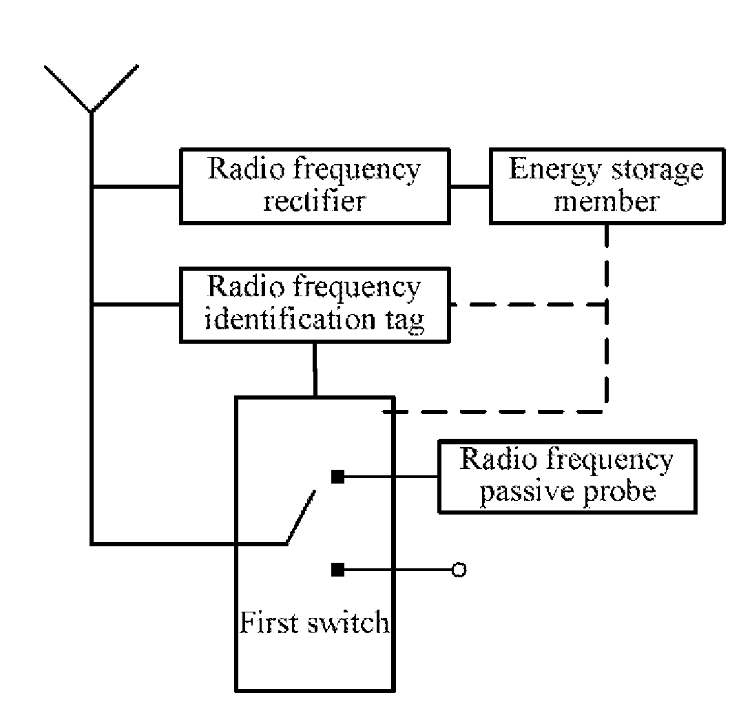
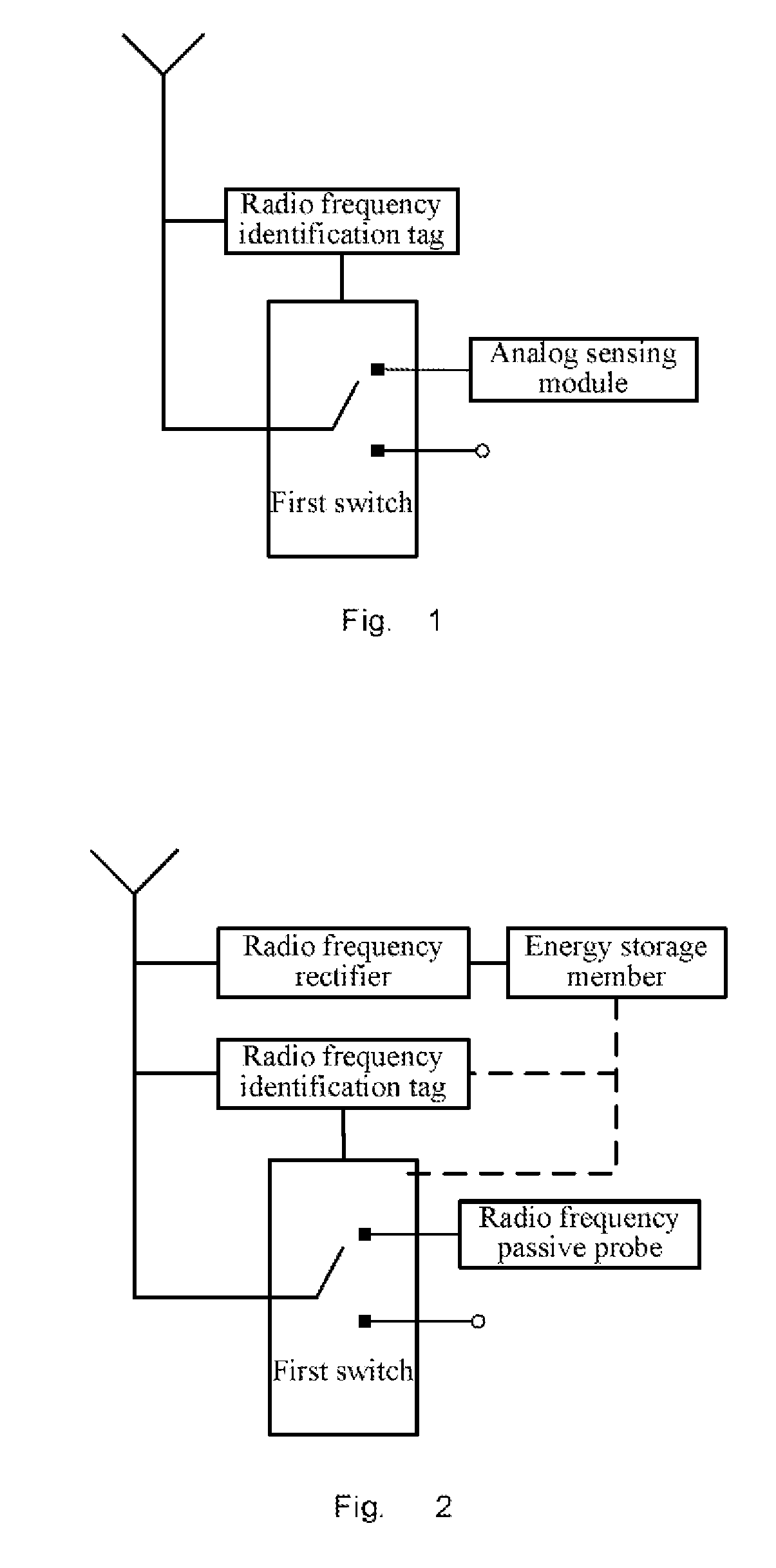
[0048]the present invention relates to a sensor, and FIG. 1 is a schematic diagram of the sensor. As shown in FIG. 1, the above sensor comprises a radio frequency identification tag, a first switch and an analog sensing module, wherein:

[0049]The radio frequency identification tag performs a digital communication with a telemeter and judges whether a preset address code matches with a target address code of the telemeter according to a digital communication signal received from the telemeter in a digital communication mode; wherein if not matched, the sensor maintains the digital communication mode, and if matched, the sensor is a target sensor, and the radio frequency identification tag of the target sensor turns on the first switch so that the target sensor enters an analog sensing mode; and in the analog sensing mode, the radio frequency identification tag of the target sensor turns off the first switch after the analog sensing module has reflected an analog sensing signal so that...

third embodiment

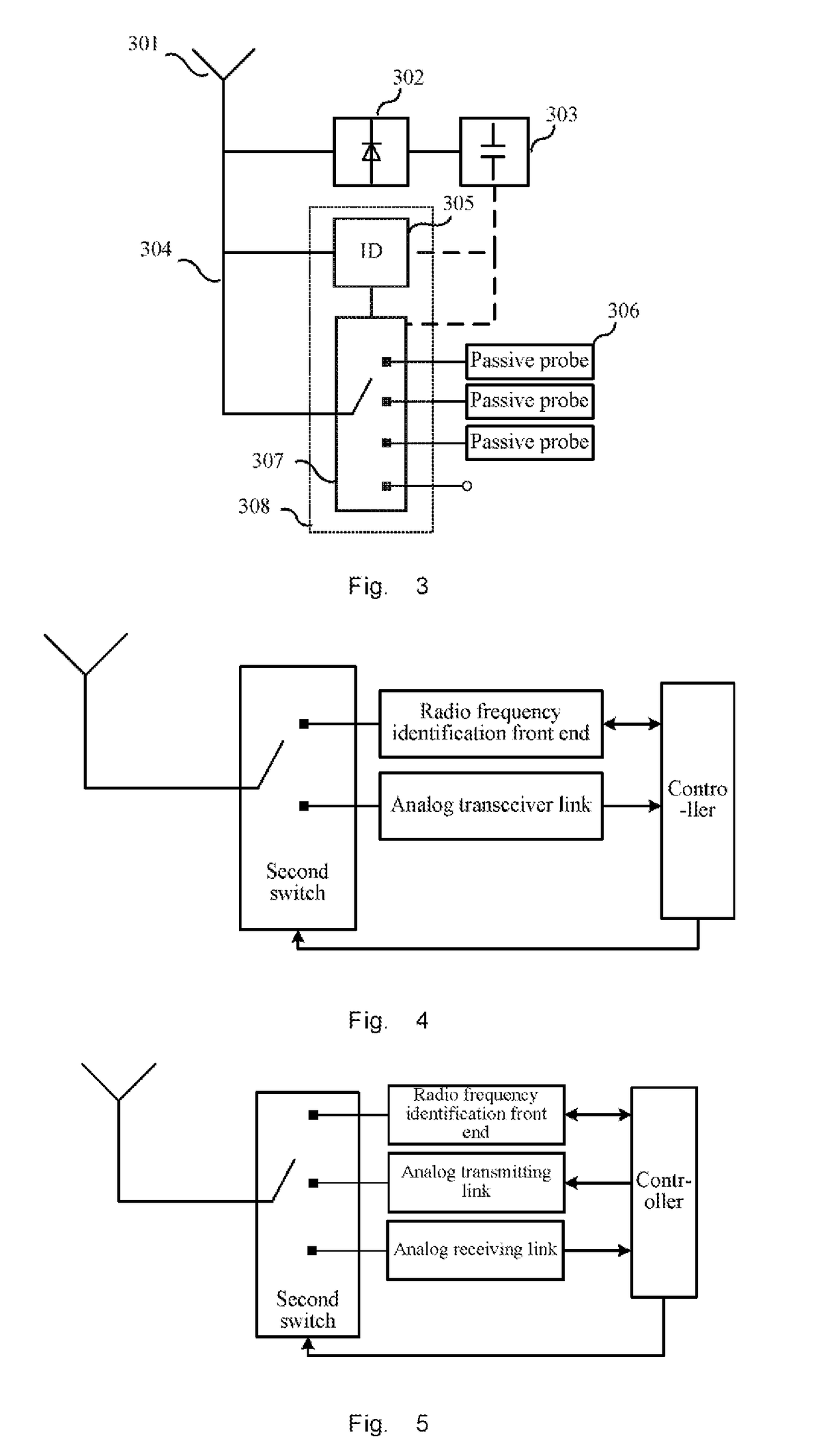
[0091]the present invention relates to a telemeter, and FIG. 4 is a schematic diagram of the telemeter. As shown in FIG. 4, the telemeter comprises:

[0092]a second switch that selects an analog transceiver link or a radio frequency identification front end to communicate with a sensor;

[0093]a radio frequency identification front end;

[0094]an analog transceiver link that radiates a target sensor with a radio frequency electromagnetic wave, receives an analog sensing signal from the target sensor and transmits the analog sensing signal to a controller in an analog sensing mode (it can be understood that, in other embodiments of the present invention, the analog transceiver link may not radiate the target sensor with the radio frequency electromagnetic wave and only receives the analog sensing signal from the target sensor);

[0095]a controller that controls the second switch to throw to the radio frequency identification front end and controls the radio frequency identification front end...

sixth embodiment

[0126]the present invention relates to a method of using sensor. FIG. 9 is a flowchart of the method of using sensor.

[0127]The sensor comprises a radio frequency identification tag, a first switch and an analog sensing module, and the first switch turns on or turns off an analog communication between the analog sensing module and the telemeter. As shown in FIG. 9, the use method of sensor comprises the following steps:

[0128]In step 901, the sensor works in a digital communication mode, and the radio frequency identification tag performs a digital communication with a telemeter.

[0129]Then in step 902, the radio frequency identification tag judges whether a preset address code matches with a target address code of the telemeter according to a digital communication signal received from the telemeter; if not matched, then it proceeds to step 906, and if matched, the sensor is a target sensor and then it proceeds to step 903.

[0130]In step 903, the radio frequency identification tag of th...


PUM


Abstract

The present invention relates to sensor system. Disclosed are a sensor, a telemeter, a wireless sensor system and a use method therefor. The wireless sensor system of the present invention comprises a telemeter and at least one sensor. The sensor and the telemeter switch between a digital communication mode and an analog sensing mode, where the digital communication mode is used for finding and activating a target sensor on basis of whether or not a target address coding matches with a preset address coding, the analog sensing mode is used for transmitting an analog sensing signal of the target sensor to extract a to-be-extracted sensitive variable, remaining sensors are in a standby state and do not reflect a sensing signal, and only an address coding used for a chip select of sensors. This fundamentally prevents a conflict of multiple sensors in a same communication area, and allows for an increased volume to be provided by utilizing a limited code length, reliably increases sensor capacity in a frequency band and measurement accuracy and speed, reduces power consumption and expands communication range, and allows sensors to be used in near-field coupling and intermediate-remote distance telemetry.

Description

FIELD OF THE INVENTION[0001]The present invention relates to a sensor system, and particularly to a sensor, a telemeter, a wireless sensor system and a use method therefor.BACKGROUND OF THE INVENTION[0002]Numbering a plurality of wireless sensors coexisting in a communication area and distinguishing the plurality of wireless sensors during monitoring may be generally referred to as a sensor multiple access technology, which has become one of core technologies of wireless sensor networks. Thereby, each measured sensitive variable can be associated with a sensor having a specific number, so as to determine a processing mode, calibration coefficients, a physical location and a measured object and so on for the sensitive variable, which is very beneficial to the monitoring and maintenance of system operation states. Especially for a wireless passive sensor, how to integrate a multiple access function without external power supply is a technical challenge which must be faced with.[0003]T...

Claims


Application Information

Patent Timeline
Patent Type & Authority Applications(United States)
IPC IPC(8): H04Q9/00H04L29/08G06K7/10
CPCH04Q9/00H04Q2209/47H04L67/12G06K7/10366
Inventor ZHENG, QIHONGLI, ZECHEN
Owner SH
Why Eureka
Try Eureka