
Circuit device, oscillator, electronic apparatus, and moving object

Active Publication Date: 2017-05-18
SEIKO EPSON CORP
View PDF4 Cites 3 Cited by
  • Summary
  • Abstract
  • Description
  • Claims
  • Application Information

AI Technical Summary

Benefits of technology

This patent describes a circuit device that can reduce power consumption in a power supply. It does this by using a digital oscillator that compensates for changes in temperature using a reference voltage generated from the difference in work functions between transistors. This reference voltage is supplied as the power supply voltage to the digital temperature compensated oscillator, which results in better phase noise and a higher power supply rejection ratio. The reference current generation circuit is separated from other circuits to improve the accuracy of the oscillation signal. Additionally, the voltage of a specific node is fixed to reduce the influence of voltage variation. The patent also mentions the use of a third transistor and a capacitor to improve the frequency characteristics of the power supply rejection ratio.

Problems solved by technology

In such a circuit configuration, while a power supply having low noise and low temperature characteristics is obtained, reduction in power consumption is difficult.
The bandgap reference circuit used in the internal power supply circuit is difficult to maintain in a high PSRR when current consumption decreases, and it is difficult to reduce power consumption in a low noise condition.

Method used


Image

  • Circuit device, oscillator, electronic apparatus, and moving object
  • Circuit device, oscillator, electronic apparatus, and moving object
  • Circuit device, oscillator, electronic apparatus, and moving object

Examples


Embodiment Construction

[0049]Hereinafter, a preferred embodiment of the present disclosure will be described in detail. This embodiment described below does not unduly limit the scope of the present disclosure described in the appended claims, and all configurations described in this embodiment are not necessarily essential as solving means of the present disclosure.

1. Configuration

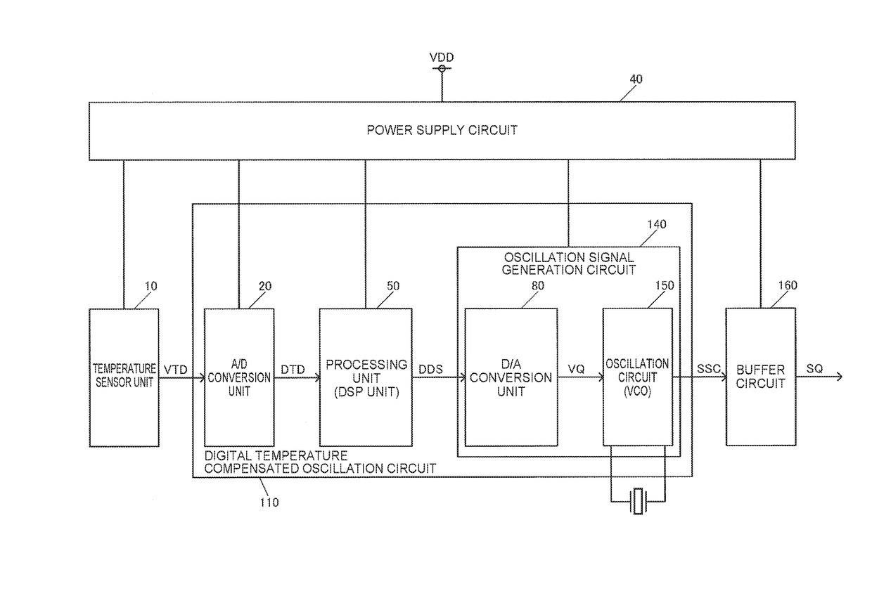
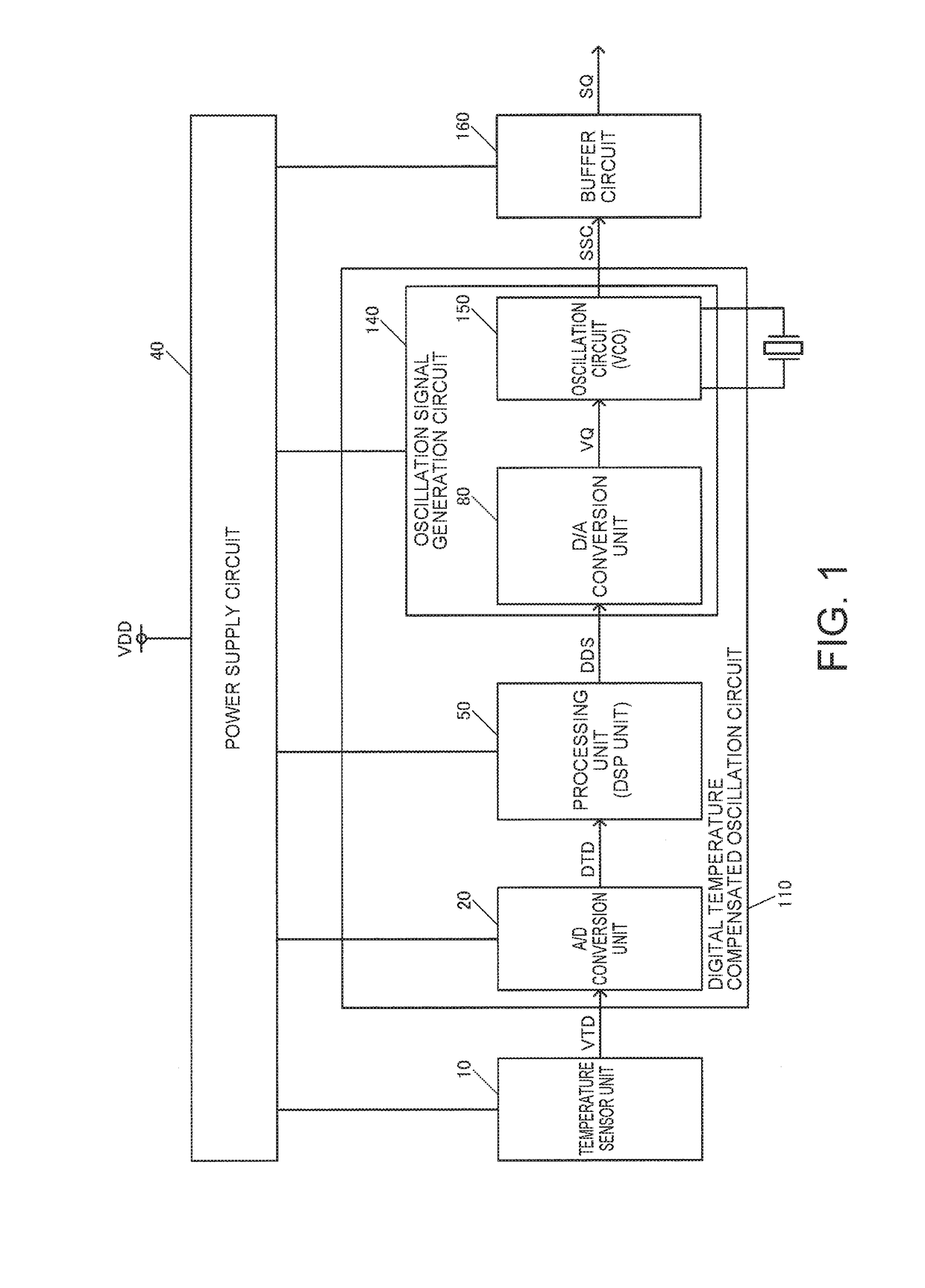
[0050]FIG. 1 shows an example configuration of a circuit device of this embodiment. The circuit device may be a semiconductor chip that is configured as a digital oscillator, such as a DTCXO or an oven controlled crystal oscillator (OCXO). For example, the circuit device and a vibrator XTAL are housed in a package, whereby a digital oscillator is realized.

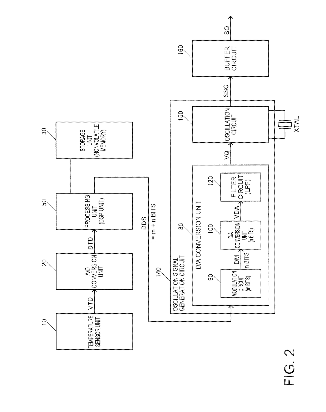
[0051]The circuit device of FIG. 1 includes a digital temperature compensated oscillation circuit 110 and a power supply circuit 40. The digital temperature compensated oscillation circuit 110 includes an A / D conversion unit 20, a processing unit 50, and an oscillation signal ...


PUM


Abstract

A circuit device includes a power supply circuit and a digital temperature compensated oscillation circuit. The digital temperature compensated oscillation circuit includes an A / D conversion unit, a processing unit, and an oscillation signal generation circuit. The A / D conversion unit performs A / D conversion of a temperature detection voltage from a temperature sensor unit. The processing unit performs temperature compensation processing of an oscillation frequency based on temperature detection data. The oscillation signal generation circuit generates an oscillation signal of the oscillation frequency using frequency control data and a vibrator. The power supply circuit includes at least one reference voltage generation circuit that generates a reference voltage based on a work function difference between transistors. The power supply circuit supplies the reference voltage generated by the reference voltage generation circuit to the digital temperature compensated oscillation circuit as a power supply voltage.

Description

BACKGROUND[0001]1. Technical Field[0002]The present disclosure relates to a circuit device, an oscillator, an electronic apparatus, a moving object, and the like.[0003]2. Related Art[0004]A temperature compensated oscillator called a temperature compensated crystal oscillator (TCXO) is known. The TCXO is used as a reference signal source in, for example, a portable communication terminal, a GPS related apparatus, a wearable apparatus, an on-vehicle apparatus, or the like.[0005]The TCXO includes an ATCXO which is an analog temperature compensated oscillator and a DTCXO which is a digital temperature compensated oscillator. An example of an ATCXO is disclosed in JP-A-2012-199631. An example of a DTCXO is disclosed in JP-A-64-82809.[0006]Since an oscillator, such as a TCXO, requires extremely high frequency accuracy, a power supply having characteristics, such as low noise and low temperature characteristics, is used. In an analog oscillator, such as an ATCXO, a linear regulator of a l...

Claims


Application Information

Patent Timeline
IPC IPC(8): H03L1/04H03L5/00H03L1/02
CPCH03L1/04H03L5/00H03L1/028H03B5/04H03B5/366H03L1/022H03L1/00H03L1/026
Inventor FUKUZAWA, AKIHIRO
Owner SEIKO EPSON CORP
Learn More