
Bearing constituent member, method of manufacturing bearing constituent member, and rolling bearing

a constituent member and bearing technology, applied in the field can solve the problems of increasing the manufacturing cost of bearing constituent members, increasing the number of processes, and increasing the toughness, and achieve the effect of long life and inexpensive manufacturing

Active Publication Date: 2017-06-15
NIPPON STEEL CORP +1
View PDF0 Cites 3 Cited by
  • Summary
  • Abstract
  • Description
  • Claims
  • Application Information

AI Technical Summary

Benefits of technology

The present invention provides a bearing constituent member that can be inexpensively manufactured and has a long lifetime even under conditions in which a foreign material is in a lubricant. The bearing constituent member has a specific surface hardness and internal hardness, as well as a specific amount of residual austenite. The method of manufacturing the bearing constituent member includes a carburizing quenching treatment and a tempering treatment. The rolling bearing includes the bearing constituent member, which can be a medium-sized tapered roller bearing. The bearing constituent member can be inexpensively manufactured and has excellent workability.

Problems solved by technology

However, in the steel disclosed in JP 4-26752 A, the nickel content, the chromium content, and the molybdenum content are high, which causes an increase in the manufacturing cost of a bearing constituent member.
However, in the medium-sized rolling bearing, relatively large-sized steel is used, and therefore, in order to secure sufficient internal hardness of the rolling bearing, it is necessary to perform a carburizing treatment or a carbonitriding treatment for a very long time period of 930 minutes as shown in FIG. 20.
In addition, in SCM steel and SNCM steel, crystal grains are coarsened due to a long time period of the carburizing treatment or the carbonitriding treatment, and toughness deteriorates.
Therefore, in a case where SCM steel or SNCM steel is used, the number of processes is increased during the manufacturing and thus the manufacturing cost is increased.

Method used


Image

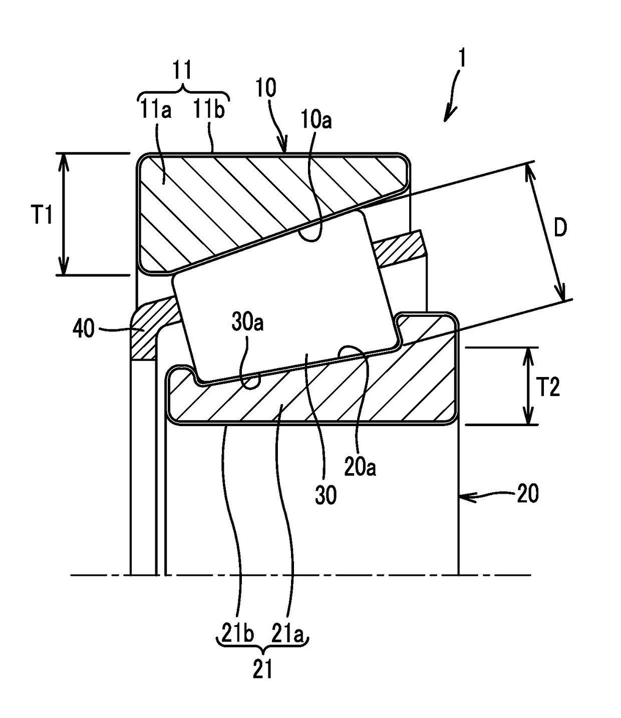
  • Bearing constituent member, method of manufacturing bearing constituent member, and rolling bearing
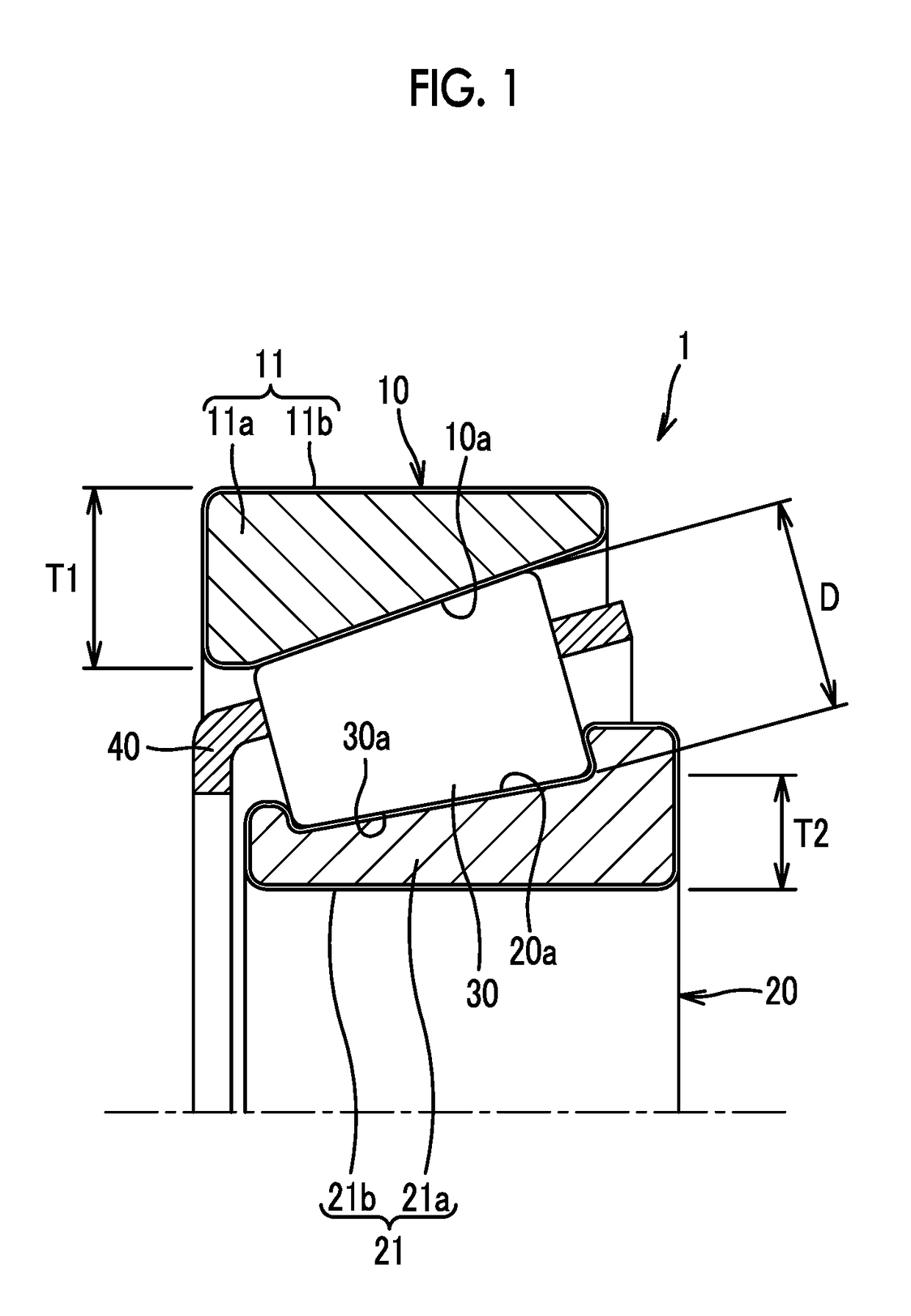
  • Bearing constituent member, method of manufacturing bearing constituent member, and rolling bearing
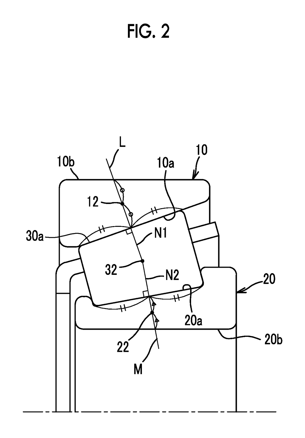
  • Bearing constituent member, method of manufacturing bearing constituent member, and rolling bearing

Examples


Embodiment Construction

;

[0030]FIG. 15 is a graph showing the results of investigating a relationship between surface Vickers hardness and the foreign material-in-oil lifetime (L10 lifetime) regarding Test Example 1;

[0031]FIG. 16 is a table showing steel which is used in each of Examples 1 to 5 and Comparative Examples 1 to 5;

[0032]FIG. 17 is a table showing the heat treatment conditions of Examples 1 to 5 and Comparative Examples 1 to 5;

[0033]FIG. 18 is a table showing conditions of a rolling fatigue test;

[0034]FIG. 19 is a table showing the results of Test Example 1; and

[0035]FIG. 20 is a diagram showing heat treatment conditions in a case where SNCM steel is used as a raw material during the manufacturing of a bearing constituent member of the related art.

DETAILED DESCRIPTION OF EMBODIMENTS

[0036]Hereinafter, a rolling bearing and a bearing constituent member according to an embodiment of the invention will be described using the accompanying drawings. Hereinafter, a case where each of an outer ring and ...


PUM

PropertyMeasurementUnit
Temperatureaaaaaaaaaa

Abstract

A bearing constituent member includes a base material including steel and a carbonitrided layer that is a surface layer on the steel, the steel including 0.3 to 0.45 mass % of carbon, 0.5 mass % or lower of silicon, 0.4 to 1.5 mass % of manganese, 0.3 to 2 mass % of chromium, 0.1 to 0.35 mass % of molybdenum, 0.2 to 0.4 mass % of vanadium, and a remainder of iron and unavoidable impurities. Surface Vickers hardness at a position at a depth of 50 μm from a surface of a rolling sliding surface is 700 to 800, internal hardness is 550 to 690 in terms of Vickers hardness, and an amount of residual austenite in a range from the surface to a depth of 10 μm is at least 30 vol %.

Description

INCORPORATION BY REFERENCE[0001]The disclosure of Japanese Patent Application No. 2015-240441 filed on Dec. 9, 2015 including the specification, drawings and abstract is incorporated herein by reference in its entirety.BACKGROUND OF THE INVENTION[0002]1. Field of the Invention[0003]The present invention relates to a bearing constituent member, a method of manufacturing the bearing constituent member, and a rolling bearing including the bearing constituent member.[0004]2. Description of Related Art[0005]In order to lubricate a rolling bearing, a lubricant is used. A foreign material such as wear debris may be in the lubricant. In a case where a rolling bearing is used under conditions in which a foreign material is in a lubricant, the foreign material is pressed against outer and inner rings or a rolling element, and surfaces of the outer and inner rings or a surface of the rolling element may be damaged. A portion in the surface that is damaged by a foreign material causes fatigue s...

Claims


Application Information

Patent Timeline
IPC IPC(8): F16C33/62F16C33/64C23C8/32C22C38/24C21D1/06C22C38/22C22C38/02C22C38/04F16C19/36C21D9/40
CPCF16C33/62F16C19/364F16C33/64C23C8/32C22C38/24C21D1/06C22C38/22C22C38/02C22C38/04C21D9/40C21D1/18C22C38/44C22C38/46F16C33/34C23C8/80F16C2204/64F16C2202/04F16C2223/16Y02P10/20
Inventor SADA, TAKASHIKANETANI, KOHEISHIMANO, TAKAHIROHIRONAKA, TETSUYANEISHI, YUTAKAYAMASHITA, TOMOHIRO
Owner NIPPON STEEL CORP
Learn More