

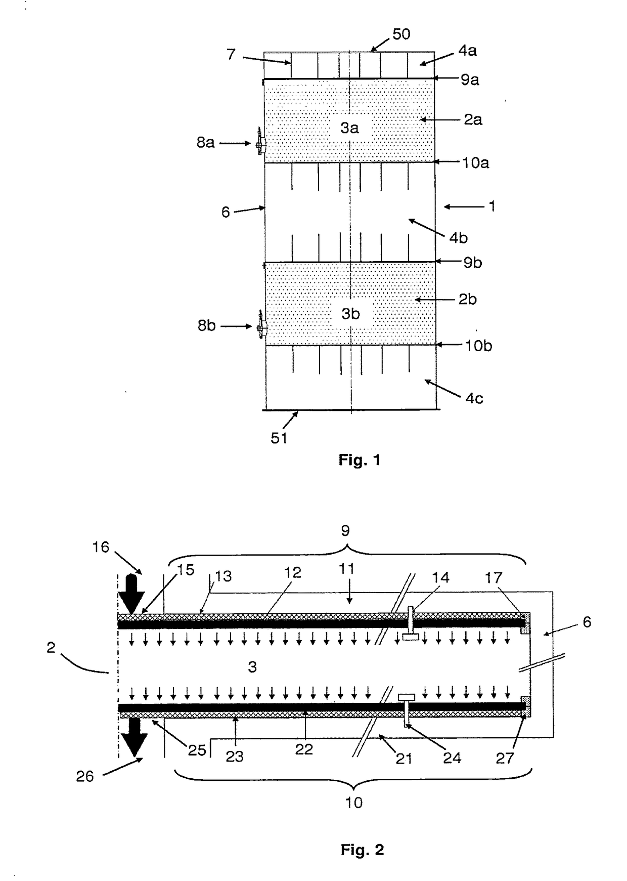
Fluid distribution unit for a chromatography column
a technology for chromatography and fluid distribution, which is applied in the direction of filtration separation, separation processes, instruments, etc., can solve the problems of system system may also entail a significant cost, and loss of efficiency, so as to overcome the drawbacks, simplify the design, and reduce the cost
- Summary
- Abstract
- Description
- Claims
- Application Information
AI Technical Summary
Benefits of technology
Problems solved by technology
Method used
Image

Examples
example 1
[0174]A circular column having a diameter of one meter over a height of one meter was made, and a distributor according to the invention was used with different parameters.
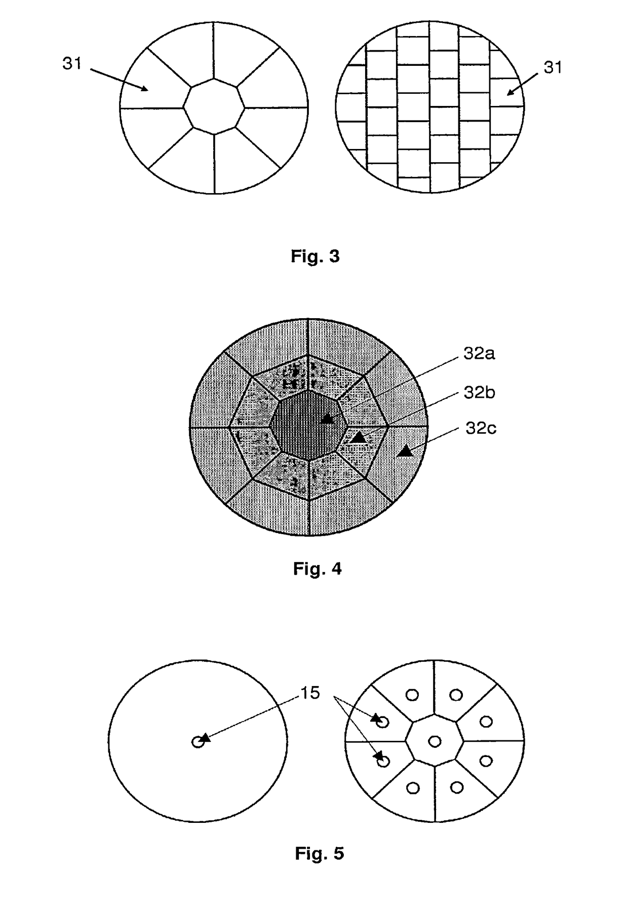
[0175]In all the tests carried out, a strong cationic resin in a calcium form was used with an average particle size comprised between 300 and 320 μm. The spacing device of the lower distributor consisted of a 3 mm-high grid.
[0176]The spacing device of the upper distributor also consisted of a 3 mm-high grid. It ensured a spacing between the floor and the resistive medium of 3 mm. The assembly was attached to the floor by a set of screws and stainless steel washers.
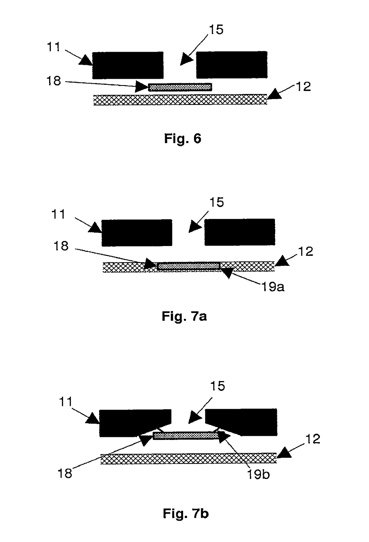
[0177]The resistive medium ensured a pressure drop of the order of 15 mbar when water flowed at a velocity of 2 m / h at room temperature. It consisted of two plates welded to each other.
[0178]Efficiency tests were carried out at various velocities by injections of 600 mL of calcium chloride at 0.1 g / L
[0179]The measured efficiencies of the device were:[01...
example 2
[0183]In this example, the same experimental setup as in Example 1 was used again, except for the resistive medium itself. Its composition was substantially different, as it did not comprise any elements welded together. The generated pressure drop remained at 15 mbar during a water flow at a velocity of 2 m / h at room temperature.
[0184]Efficiency tests were carried out at various velocities with injections of 600 mL of calcium chloride at 0.1 g / L
[0185]The measured efficiencies of the device were:[0186]660 theoretical plates at a velocity of 1 m / h;[0187]480 theoretical plates at a velocity of 2 m / h; and[0188]400 theoretical plates at a velocity of 3 m / h.
example 3
[0189]In this example, the same experimental setup as in Example 2 was used again, except for the additional presence of a deflector having a diameter of 80 mm, a thickness of 1 mm, and maintained at a 1 mm spacing from the injection point.
[0190]Efficiency tests were carried out at various velocities with injections of 600 mL of calcium chloride at 0.1 g / L
[0191]The measured efficiencies of the device were:[0192]670 theoretical plates at a velocity of 1 m / h;[0193]500 theoretical plates at a velocity of 2 m / h; and[0194]420 theoretical plates at a velocity of 3 m / h.
PUM
| Property | Measurement | Unit |
|---|---|---|
| Temperature | aaaaa | aaaaa |
| Length | aaaaa | aaaaa |
| Diameter | aaaaa | aaaaa |
Abstract
Description
Claims
Application Information