Piezoelectric device for ultrasonic sensor

a technology of ultrasonic sensor and piezoelectric device, which is applied in piezoelectric/electrostrictive/magnetostrictive devices, mechanical vibration separation, electrical apparatus, etc., can solve the problems of deteriorating the receiving properties of the ultrasonic sensor, and reducing the polarization of the piezoelectric element. , to prevent the disconnection and prevent the separation of the second iridium layer

Active Publication Date: 2017-06-22
SEIKO EPSON CORP
View PDF2 Cites 5 Cited by
  • Summary
  • Abstract
  • Description
  • Claims
  • Application Information

AI Technical Summary

Benefits of technology

[0017]According to this configuration, it is possible to prevent the disconnection between the electrodes by preventing the separatio

Problems solved by technology

However, if the Ir is used as an electrode material, there is a possibility that the residual amount of polarization of the piezoelectric element is reduced, and the receiving properties of the ultrasonic sensor are deteriorated.
However, since the residual amount of polarization is reduced than a case where the Pt is applied as

Method used


Image

  • Piezoelectric device for ultrasonic sensor
  • Piezoelectric device for ultrasonic sensor
  • Piezoelectric device for ultrasonic sensor

Examples


embodiment 1

Ultrasonic Device

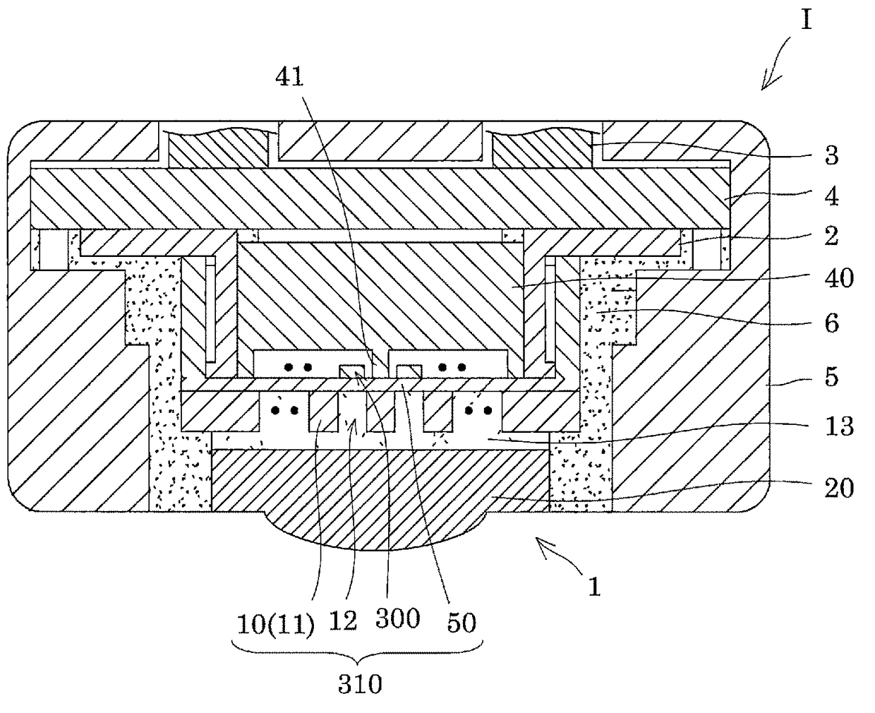
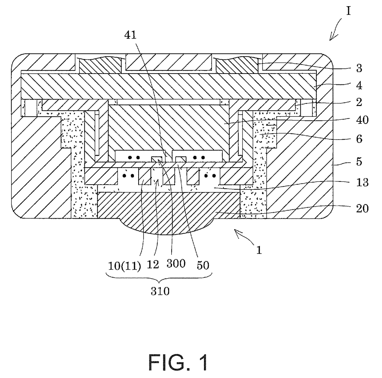
[0046]FIG. 1 is a cross-sectional view illustrating a configuration example of an ultrasonic device equipped with an ultrasonic sensor. As illustrated in the drawings, an ultrasonic probe I is configured by equipped with a CAV surface type ultrasonic sensor 1, a flexible printed circuit board (FPC board 2) which is connected to the ultrasonic sensor 1, a cable 3 extracted from a device terminal (not illustrated), a relay substrate 4 for connecting between the FPC board 2 and the cable 3, a housing 5 for covering the ultrasonic sensor 1, the FPC board 2, and the relay substrate 4, a water-resistant resin 6 for filling between the hosing 5 and the ultrasonic sensor 1, or the like.

[0047]The ultrasonic waves are transmitted from the ultrasonic sensor 1. In addition, the ultrasonic waves which are reflected from the measurement object are received by the ultrasonic sensor 1. In the device terminal of the ultrasonic probe I, information (position, shape, or the like) rela...

example 1

Preparation of PZT Precursor Solution

[0108]A PZT precursor solution was manufactured such that an acetic acid and water are weighed to a container, and lead acetate, zirconium butoxide, titanium tetra-i-propoxide, and polyethylene glycol were weighed, and these materials were heated for 90° C. and stirred.

Manufacturing of Vibrating Plate

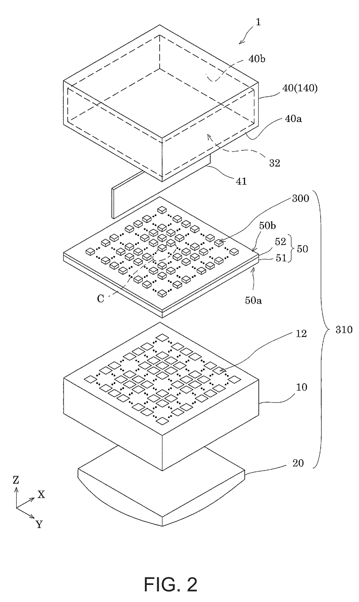
[0109]By thermally oxidizing a silicon substrate (wafer 110) having a size of 6 inch, a silicon dioxide film (elastic film 51) was formed on the substrate. Next, the zirconium film was formed by the sputtering method, and a zirconium oxide film (insulation layer 52) was obtained by thermal oxidation.

[0110]By these processes, the vibrating plate 50 including a silicon dioxide film and a zirconium oxide film is manufactured.

Manufacturing of First Electrode Layer

[0111]On the vibrating plate 50 (on the zirconium oxide film (insulation layer 52)), a titanium layer, a platinum layer, an iridium layer, and a titanium layer were formed in this order by the s...

example 2

[0123]In Example 2, by patterning formation which is different from Example 1, patterning of the first electrode layer 60, the piezoelectric layer 70, and the second electrode layer 80 was performed, and the piezoelectric element 300 including the first electrode layer 60, the piezoelectric layer 70, and the second electrode layer 80 which includes the platinum layer (lower layer side electrode 80a) and the iridium layer (upper layer side electrode 80b) was completed.

[0124]Thereafter, a silicon dioxide film which was formed on a surface opposite to the piezoelectric element 300 with the vibrating plate 50 therebetween of a silicon substrate (wafer 110) was removed by grinding process and the Si of the silicon substrate was grinded so as to make the thickness of the substrate to 150 μm, thereby forming the cavity (CAV) having a predetermined shape by the dry etching. Next, a metallic back plate was bonded to the grinded surface with the adhesive so as to cover the CAV. Next, the lens...


PUM


Abstract

A piezoelectric device includes a substrate with a cavity, a vibrating plate which is provided on the substrate so as to block an opening surface of the cavity, and a piezoelectric element which is provided on a surface of the vibrating plate opposite to the cavity, including a first electrode, a piezoelectric layer, and a second electrode, in which the second electrode has a laminated structure including a Pt layer (lower layer side electrode) and an Ir layer (upper layer side electrode), in which the Pt layer is in contact with the piezoelectric layer, and in which, if it is assumed that two directions which are parallel to a surface of the substrate and mutually perpendicular are defined as an X direction and a Y direction, the Ir layer is extended to an outside of the cavity at least in the X direction on an X-Y plane view.

Description

BACKGROUND[0001]1. Technical Field[0002]The present invention relates to a piezoelectric device for an ultrasonic sensor.[0003]2. Related Art[0004]In the related art, an ultrasonic sensor using electromechanical transformation characteristics of a piezoelectric element is provided. In the ultrasonic sensor, an ultrasonic wave (transmitting ultrasonic wave) is transmitted by driving the piezoelectric element by supplying electric signals to the piezoelectric element. In addition, the piezoelectric element receives the ultrasonic wave (reflected ultrasonic wave) which is reflected from a measurement object, thereby driving the piezoelectric element and obtaining the electric signals. In the ultrasonic device equipped with the ultrasonic sensor, information (positions, shapes, or the like) relating to the measuring object is detected based on these electric signals, that is, waveform signals of the transmitting ultrasonic wave or the reflected ultrasonic wave.[0005]This type of the ult...

Claims


Application Information

Patent Timeline
IPC IPC(8): H01L41/047B06B1/06
CPCB06B1/0622H01L41/0477B06B1/0629H10N30/877H10N30/2047
Inventor YONEMURA, TAKAYUKIONOGI, TOMOHIDEKOJIMA, CHIKARA
Owner SEIKO EPSON CORP
Why Eureka
Try Eureka