

Ceramic structure, method for manufacturing the same, and member for semiconductor manufacturing apparatus
a ceramic structure and ceramic technology, applied in the direction of ohmic-resistance heating, electric heating, basic electric elements, etc., can solve the problems of reduce cracking or breakage probability, and reduce the effect of heat loss
- Summary
- Abstract
- Description
- Claims
- Application Information
AI Technical Summary
Benefits of technology
Problems solved by technology
Method used
Image

Examples
examples
[0025](1) Method for Manufacturing Ceramic Structure
[0026](1-1) Preparation of First Substrate
[0027](1-1-1) Preparation of Raw Powders
[0028]A commercially available high-purity fine powder (oxygen content: 0.9%, impurity component other than oxygen: 0.1% or less, average particle size: 1.1 μm) was used as an AlN raw material. A commercially available high-purity fine powder (purity: 99.9% or more, average particle size: 1 μm) was used as a Y2O3 raw material. The AlN raw material and the Y2O3 raw material weighed at a mass ratio in the range of 95:5 to 100:0, together with φ20-mm iron-core nylon cobblestones, were wet-blended in an alcohol solvent in a nylon pot for 4 hours. After blending, the resulting slurry was removed and was dried in a nitrogen stream at 110° C. The dried product was passed through a 30-mesh sieve to prepare a blended powder.
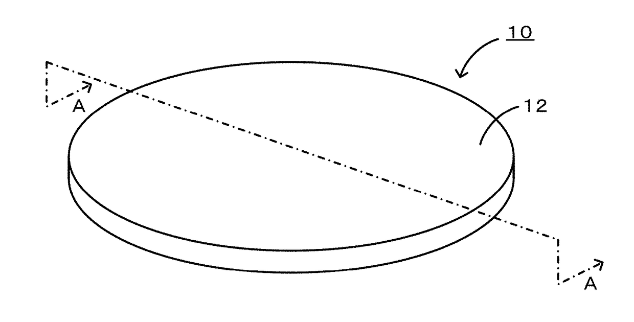
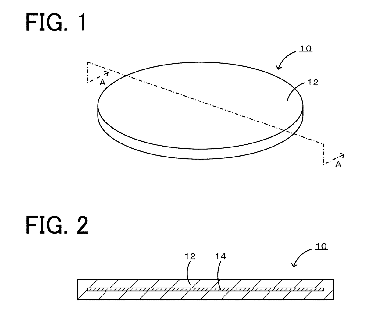
[0029](1-1-2) Manufacture of Disk-Shaped Formed Body
[0030]The powder prepared in (1-1-1) was uniaxially pressed at a pressure of 200 kgf / c...
experimental examples 1 to 3
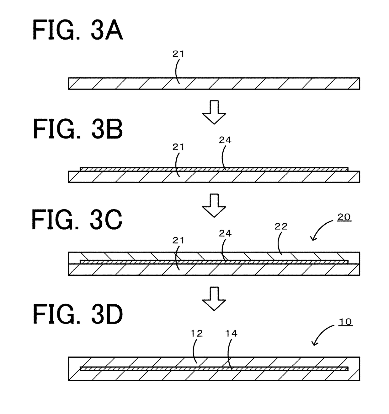
[0055]In Experimental Examples 1 to 3, the material of the heater electrode was a WC / Ru composite material, in which Ru was added to the main component WC. The thermal expansion coefficient of Ru was measured to be 7.64 ppm / ° C., which was greater than the thermal expansion coefficient of AlN or WC. According to literature, Ru has a low resistivity of 8×10⁻⁶ Ωcm at roman temperature. The electrode composition was WC / 2.5% by volume Ru (which means that the volume of Ru is 2.5% of the total volume) in Experimental Example 1, WC / 7.5% by volume Ru in Experimental Example 2, or WC / 16% by volume Ru in Experimental Example 3. The first substrate, the electrode paste, and the second substrate were stacked in this order and were fired in a nitrogen atmosphere at a pressing pressure of 200 kgf / cm2 and at a maximum temperature of 1825° C. for 4 hours to prepare a sample of each experimental example. In Experimental Example 1, the heater electrode had a thermal expansion coefficient of 5.35 ppm...
experimental examples 4 to 8
[0056]In Experimental Examples 4 to 8, the material of the heater electrode was a WC / RuAl composite material, in which RuAl was added to WC. The thermal expansion coefficient of RuAl was measured to be 10.3 ppm / ° C., which was still greater than the thermal expansion coefficient of Ru. Thus, the addition of RuAl in a smaller amount than Ru can increase the thermal expansion coefficient of the WC electrode, and RuAl can be more readily adapted to the AlN ceramic substrates. The |ΔCTE| was 0.35 ppm / ° C. or less in all the experimental examples. The resistivity was 3.0×10⁻⁵ Ωcm or less in all the experimental examples. Thus, the additive amount of RuAl in the range of 1.2% to 15% by volume can result in a decreased |ΔCTE| and low resistivity. A cross-sectional observation with a SEM showed no crack at or near the interface and, unlike the addition of Ru alone, showed no layer structures having different compositions in the heater electrode. As a representative, a cross-sectional SEM ph...
PUM
| Property | Measurement | Unit |
|---|---|---|
| temperature | aaaaa | aaaaa |
| resistivity | aaaaa | aaaaa |
| pressure | aaaaa | aaaaa |
Abstract
Description
Claims
Application Information