

Solid phase microextraction coating
a microextraction coating and solid phase technology, applied in the field of solid phase microextraction coatings, can solve the problems of not being compatible with organic solvent-assisted desorption, not being able to properly embed particulate in fluorocarbon polymers, and not being able to meet the requirements of thermal desorption
- Summary
- Abstract
- Description
- Claims
- Application Information
AI Technical Summary
Benefits of technology
Problems solved by technology
Method used
Image

Examples
example 1
SPME Sampling Fiber Prepared by Multiple Dipping Cycles
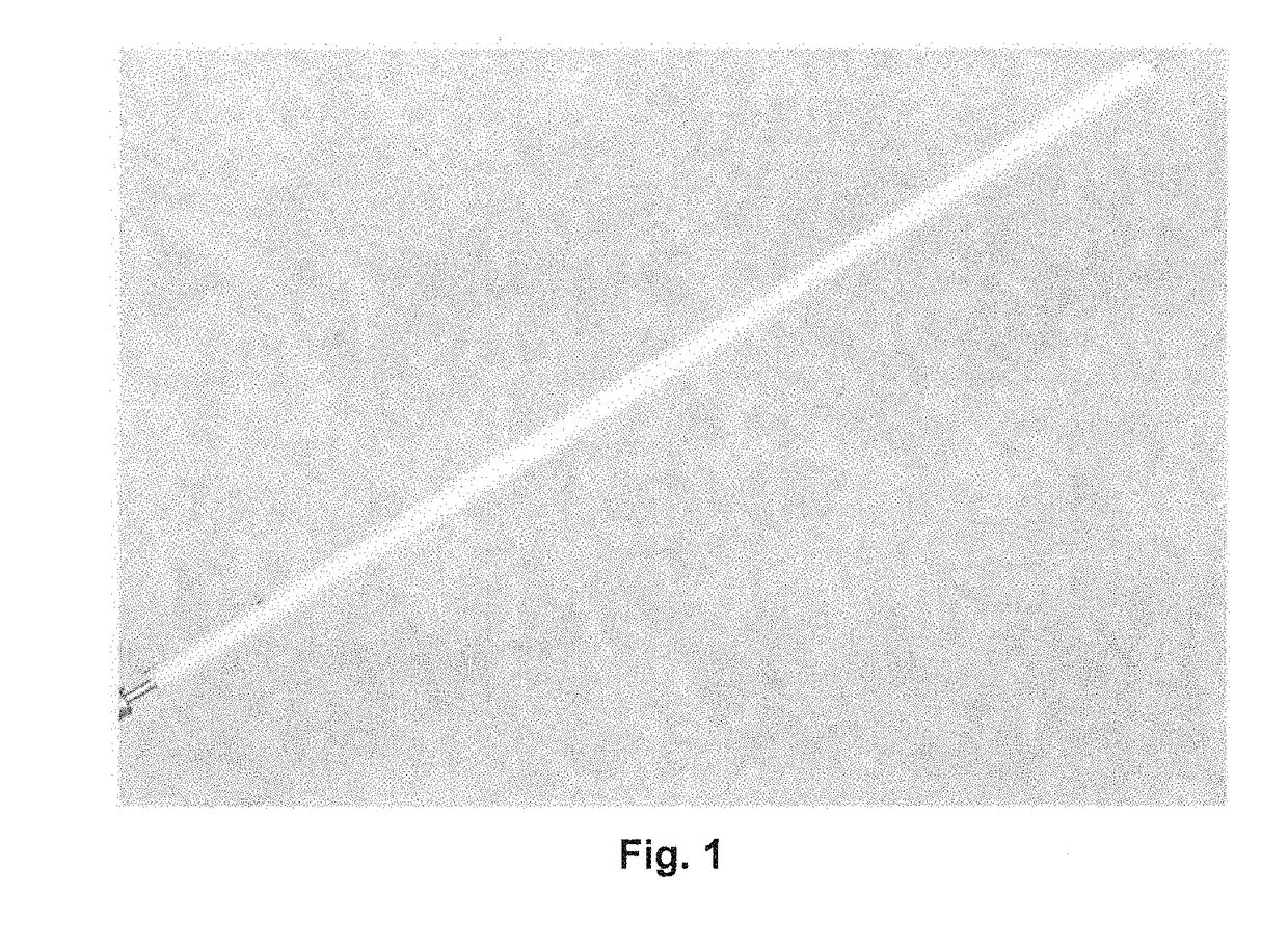
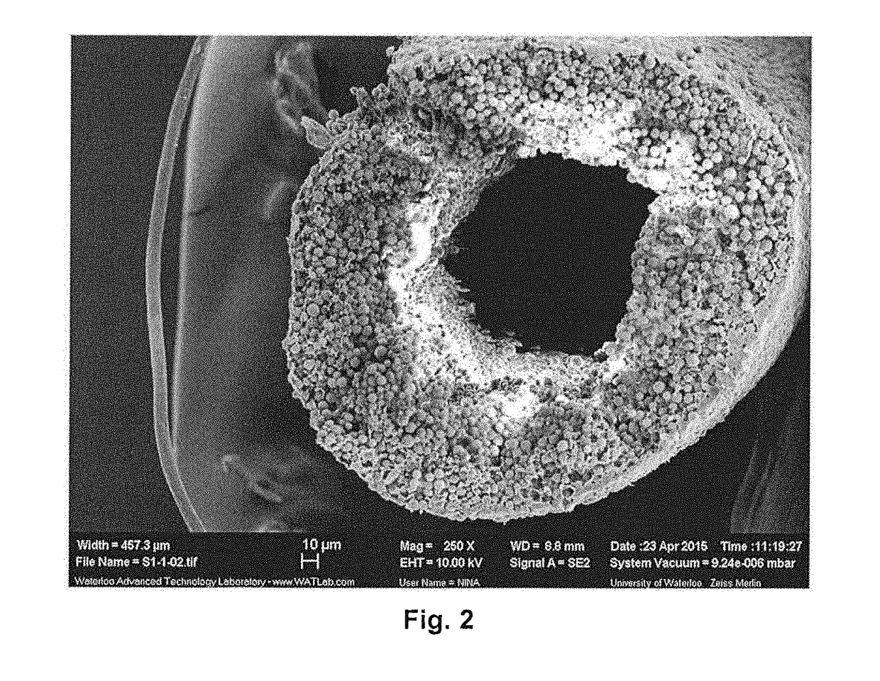
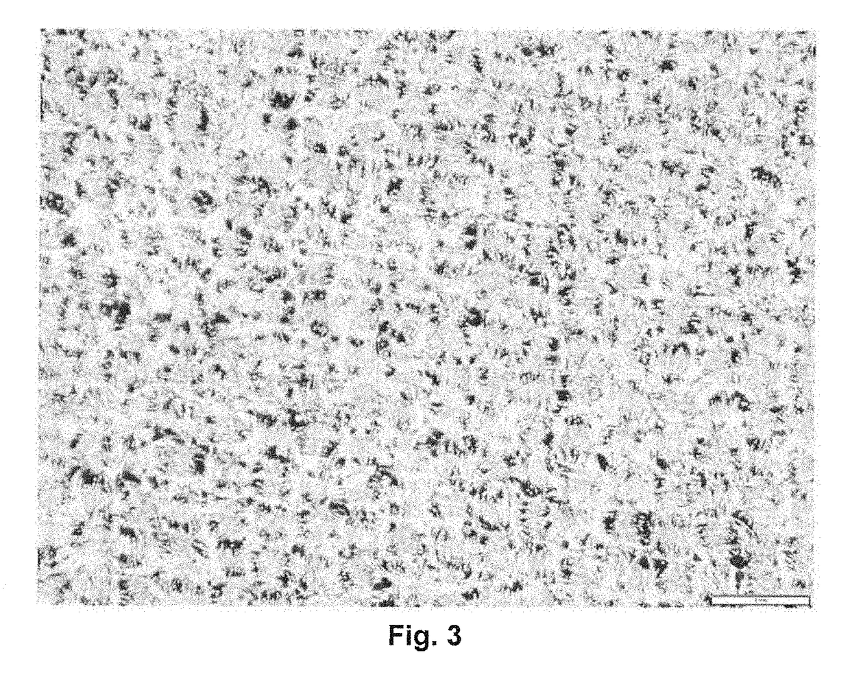
[0095]Stainless steel wires of 200 μm diameter were etched by immersion in a solution of water saturated with sodium chloride and application of a voltage of 3.5 V. Before the coating procedure, the etched substrate was sonicated in a solution water / methanol 50:50 (v / v) for 10 minutes. A coating slurry was prepared by suspending 60 mg of HLB particles (5 μm diameter) in 1.5 ml of a 2.6% (w / w) solution of PTFE AF 2400 in FC-72. FC-72 has a density of 1.68 g / cm3. Accordingly, the slurry includes about 3.8 g of FC-72, about 0.10 g of PTFE AF 2400, and 60 mg of HLB particles. The ratio of PTFE AF 2400 to particles is 1.7:1 (w / w).
[0096]The slurry was deposited on the metallic support by dipping and slowly retracting the support from the slurry. Seven application cycles were used to prepare the extraction coating. After each cycle, the fiber was left at room temperature for 1 minute to allow solvent evaporation. The resulting extracti...
example 2
SPME Sampling Fabric Prepared by Film Application
[0097]A coating slurry was prepared as described in Example 1. A carbon mesh fabric having a unit weight of 115 g / m2, a thickness of 406 microns, and a carbon content of 99%, which was not-pretreated before coating, was immobilized on the surface of a bar-coater in order to keep the fabric straight on the surface. The immobilized fabric was coated with the slurry using the film applicator at a constant spreading speed to result in a carbon mesh fabric having a thin, homogeneous coating layer thereon. The coated fabric was left to dry for a minute in order to evaporate the FC-72 solvent. The coating volume per SPME instrument is greater with the coated fabric compared to the coated wires of Example 1 and the authors of the present disclosure expect that the coated fabric will have a lower analyte detection threshold.
example 3
Analysis of Fruit Metabolites in an Aqueous Matrix Using PTFE AF2400 / HLB Fiber and GC-MS
[0098]Ultrapure water was spiked with a mixture of all the GC-amenable analytes listed in Table 1, having diverse chemical functionalities and physical chemical characteristics. The water was spiked at concentrations ranging from 8.3 to 664.4 μg of compound per liter, keeping the organic solvent volume below 1% (v / v). The spiked water sample allowed for testing extraction of all the analytes simultaneously.
[0099]The samples were extracted using the SPME sampling fiber described in Example 1 by directly exposing the coating to the sample matrix for 8 hrs at a temperature of 35° C. while shaking the sample at 500 rpm.
[0100]The desorption, separation, and detection of the analytes was performed by an Agilent 6890 / 5973 GC-MS equipped with a GERSTEL CIS septumless PTV injector. The adsorbed analytes were thermally desorbed at 250° C. for 15 minute using ultrapure helium as a carrier gas and at a flow ...
PUM
| Property | Measurement | Unit |
|---|---|---|
| Temperature | aaaaa | aaaaa |
| Fraction | aaaaa | aaaaa |
| Specific surface area | aaaaa | aaaaa |
Abstract
Description
Claims
Application Information