
Intercalation membrane

a technology of intercalation membrane and membrane, which is applied in the direction of membranes, electrolyte stream management, electrochemical generators, etc., can solve the problems of reducing the benefit of using a membrane, reducing the number of ions, and reducing so as to improve the efficiency of electrochemical transfer walls and increase the number of ions. , the effect of expanding the number of electrochemical systems

Active Publication Date: 2017-09-07
ENLIGHTEN INNOVATIONS INC
View PDF2 Cites 4 Cited by
  • Summary
  • Abstract
  • Description
  • Claims
  • Application Information

AI Technical Summary

Benefits of technology

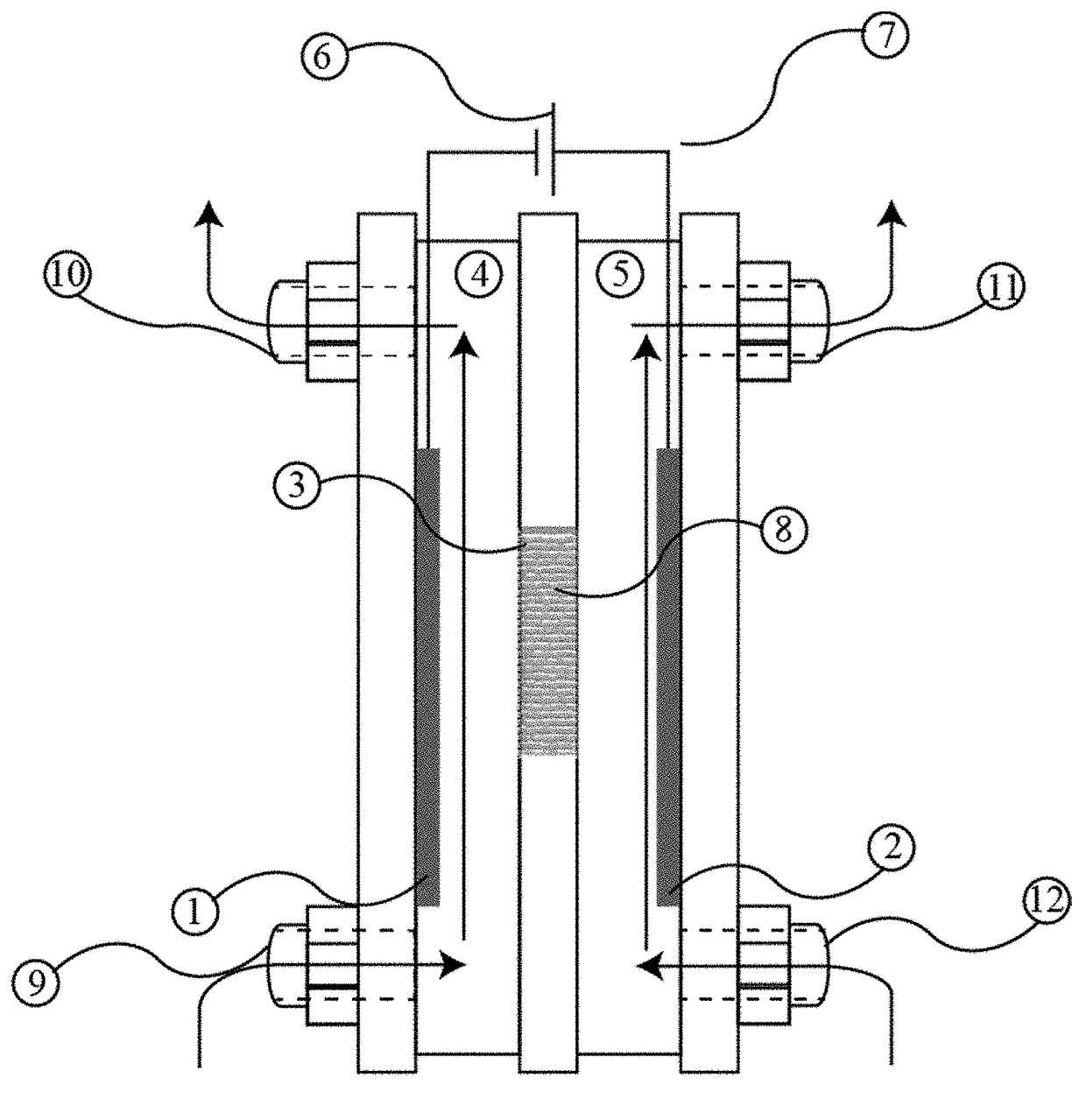
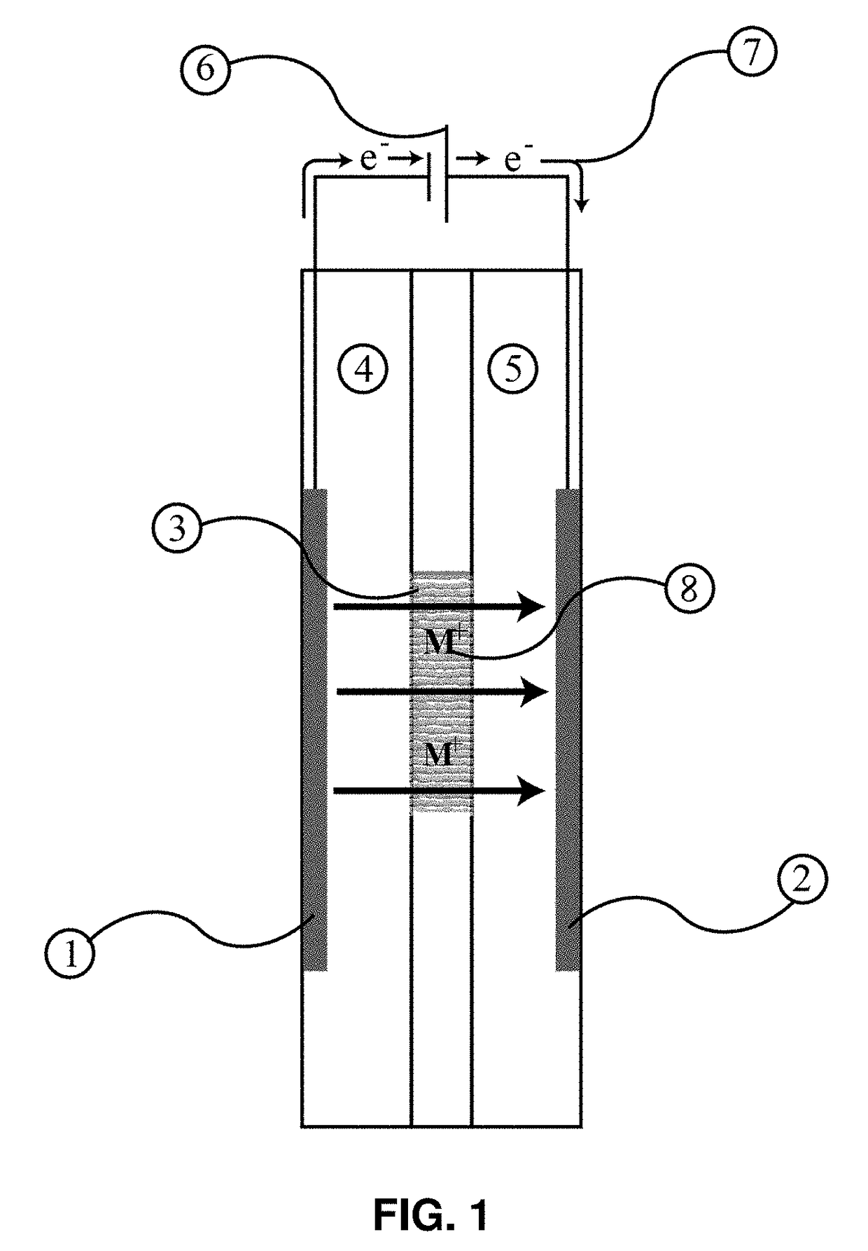
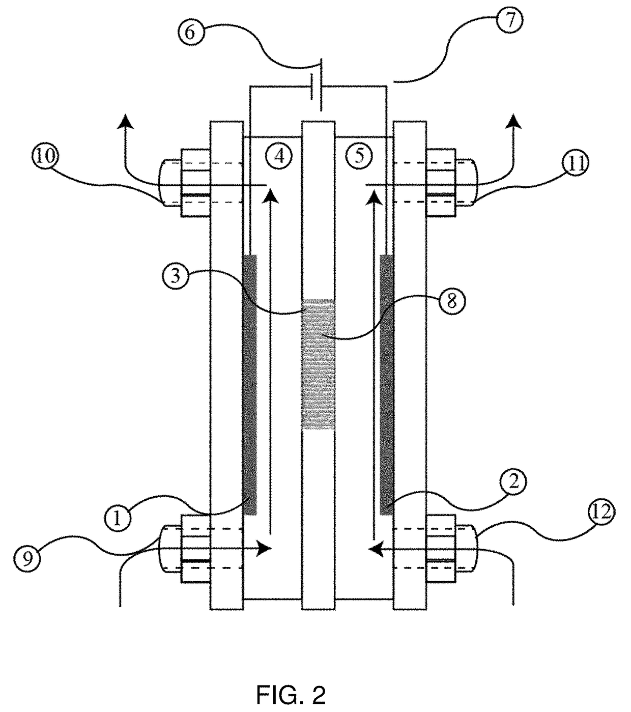
The present invention provides an electrochemical method and cell device with a dense separation membrane that uses an intercalation material to transfer ions between two isolated compartments of an electrochemical cell. This membrane allows for high current densities and the use of a large family of intercalation materials, increasing the number of ions that can be conducted and expanding the number of electrochemical systems with which it can be used. The membrane also acts as a dense ion conducting membrane and only metal or alkali metal cations will be transferred between a first medium and a second medium, separating the electrochemical reactions at the two electrodes. The membrane is also used to separate the reactions occurring at two electrodes of an electrochemical cell, improving the efficiency, selectivity, and sensitivity of the cell, while permitting non-compatible environments to be used in the same electrochemical cell.

Problems solved by technology

Currently, there are many limitations to porous ion conducting membranes or areas which industry requires improvement.
The lack of selectivity in porous ion conducting membranes reduces the benefit of using a membrane to separate the reactions occurring at the two electrodes.
In either case when the porous membranes are not under an applied electric field, the separation afforded by the electric field will be lost, and the concentration gradients generated by the electrical field will cause the ions to diffuse back through the membrane.
These types of membranes can also foul easily due to ions or other objects present in the electrolyte that are larger than the smallest pore, but smaller than the larger pores, migrating into and become lodged in the membrane, inhibiting any further ion transfer through that pathway.
One limitation with dense ion conducting membranes is there are only a limited number of known materials which conduct a limited number of ions at conditions that are amendable to practical applications.
The limitations with electrochemical transfer walls are the requirement of having an electron transfer accompany the ion transfer at the interface of the wall and first solution, the requirement of having a second electron transfer at the interface of the wall and second solution, and the limitation this forces on the current density for which the ion can be transferred across the wall (U.S. Pat. No. 8,449,747 B2, 2) or higher current densities through more elaborate cell design and setup (U.S. Publication No. 2013 / 0126354 A1).
These limitations narrow the field of use for electrochemical transfer walls to applications that can tolerate low current densities and complicated electron transfer.

Method used


Image

  • Intercalation membrane
  • Intercalation membrane
  • Intercalation membrane

Examples


example 1

[0067]An intercalation membrane was used to transfer ions from a first medium to a second medium. Na-ions were transferred from an aqueous solution of sodium sulfate in contact with the anode through an intercalation membrane and to an aqueous solution also containing sodium sulfate. The electrolytes were both made to contain 10 wt % Na2SO4 making an aqueous solution with a pH between 9 and 10. The temperature of the electrolytes was unchanged, remaining at room temperature for the duration of the experiments. Two different experiments were conducted with the system. The first consisted of a current density step experiment, where the current density was stepped up starting at 0.5 mA / cm2 to 250 mA / cm2 holding each step for 60 s. The second experiment was a bulk electrolysis experiment, in which the current density was maintained at 110 mA / cm2 for the duration of the experiment. The current 13, 15 and potential 14, 16 transients of these experiments can be seen in FIGS. 3 and 4. It ca...

example 2

[0068]An intercalation membrane was used to transfer ions from a first medium to a second medium. Li-ions were transferred from an aqueous solution of lithium sulfate in contact with the anode through an intercalation membrane and to an aqueous solution also containing lithium sulfate. The electrolytes were both made to contain 10 wt % Li2SO4 making an aqueous solution with a pH between 9 and 10. The temperature of the electrolytes was unchanged, remaining at room temperature for the duration of the experiments. Two different experiments were conducted with the system. The first consisted of a current density step experiment, where the current density was stepped up starting at 0.5 mA / cm2 to 250 mA / cm2 holding each step for 60 s. The second experiment was a bulk electrolysis experiment, in which the current density was maintained at 110 mA / cm2 for the duration of the experiment. The current 17, 19 and potential 18, 20 transients of these experiments can be seen in FIGS. 5 and 6. It ...

example 3

[0069]An intercalation membrane was used to transfer ions from a first medium to a second medium. Mg-ions were transferred from an aqueous solution of magnesium sulfate in contact with the anode through an intercalation membrane and to an aqueous solution also containing magnesium sulfate. The electrolytes were both made to contain 10 wt % MgSO4 making an aqueous solution with a pH between 9 and 10. The temperature of the electrolytes was unchanged, remaining at room temperature for the duration of the experiments. Two different experiments were conducted with the system. The first consisted of a current density step experiment, where the current density was stepped up starting at 0.5 mA / cm2 to 250 mA / cm2 holding each step for 60 s. The second experiment was a bulk electrolysis experiment, in which the current density was maintained at 110 mA / cm2 for the duration of the experiment. The current 21, 23 and potential 22, 24 transients of these experiments can be seen in FIGS. 7 and 8. ...


PUM


Abstract

An ion conductive intercalation membrane is useful to separate anode and cathode compartments in an electrochemical cell and provide ion transport between the anode and cathode compartments. The intercalation membrane does not receive and release electrons during operation of the electrochemical cell. An electric potential and current source is connected to an anode and a cathode disposed in respective anode and cathode compartments to cause oxidation and reduction reactions to occur at the anode and cathode, to cause electrons to flow through an external circuit coupled to the anode and cathode, and to cause ions to transport through the intercalation membrane to maintain charge neutrality within the electrochemical cell. The electrochemical cell operates at a current density greater than 25 mA / cm2 across the intercalation membrane.

Description

CROSS-REFERENCE TO RELATED APPLICATION[0001]This application claims the benefit of U.S. Provisional Application No. 62 / 303,242, filed Mar. 3, 2016, entitled “INTERCALATION MEMBRANE,” which patent application is hereby incorporated by reference.FIELD OF THE INVENTION[0002]The present invention relates in general to an intercalation membrane useful to transport ions between two compartments of an electrochemical cell by the application of an electrochemical potential. More specifically this invention discloses a novel membrane that can improve the functionality of electrochemical cells for a variety of applications. Some non-limiting examples are in separation, recycling, reclamation, decontamination, electrochemical synthesis, and sensors.BACKGROUND OF THE INVENTION[0003]The use of ion conducting membranes or electrochemical transfer walls to transfer ions between two separate compartments of electrochemical cells has been known for a long time. The concept is used commercially in a ...

Claims


Application Information

Patent Timeline
IPC IPC(8): H01M8/0215H01M8/18H01M8/04276C25B9/19
CPCH01M8/0215H01M8/188H01M8/04276B01D67/0046B01D71/02C02F1/46104C02F1/4672C25B13/04C25C7/04B01D2325/42C02F2201/46115Y02E60/50B01D61/461
Inventor MOSBY, JAMES M.HINKLIN, THOMAS
Owner ENLIGHTEN INNOVATIONS INC
Learn More