
Zeolite catalysts, methods for producing zeolite catalysts, and methods for producing lower olefins

a technology of zeolite catalyst and catalyst, which is applied in the field of zeolite catalyst, can solve the problems of large amount of energy consumption and insufficient propylene supply by this technique, and achieve the effects of suppressing increasing the formation of aromatic hydrocarbons, and reducing acid strength

Inactive Publication Date: 2017-10-05
CHIYODA CORP
View PDF0 Cites 3 Cited by
  • Summary
  • Abstract
  • Description
  • Claims
  • Application Information

AI Technical Summary

Benefits of technology

The patent describes a process to produce a type of catalyst called crystalline aluminosilicate. The process involves setting the molar ratios of iron atoms in the range from 0.4 to 0.7. By adjusting these ratios, researchers found that propylene can be produced at low temperatures, and the formation of aromatic hydrocarbons can be reduced. This is particularly true when iron atoms are incorporated into the MFI-type crystalline aluminosilicate. The patent also explains that naphtha, which is a type of crude oil fraction, can be used as a starting material for the process. The term "lower olefin" refers to olefins with less carbon atoms, such as ethylene and propylene. The patent also introduces the concept of the acid density of a crystalline aluminosilicate, which is the molar ratio of silicon atoms to aluminum atoms and iron atoms or to total moles of aluminum atoms, iron atoms, and gallium atoms.

Problems solved by technology

However, this process, which is non-catalytic, requires high temperatures between 800° C. and 900° C. for cracking, resulting in a large amount of energy consumption.
Therefore, propylene supply by this technique might be insufficient due to the expansion of propylene demand.

Method used


Image

  • Zeolite catalysts, methods for producing zeolite catalysts, and methods for producing lower olefins
  • Zeolite catalysts, methods for producing zeolite catalysts, and methods for producing lower olefins
  • Zeolite catalysts, methods for producing zeolite catalysts, and methods for producing lower olefins

Examples


example 5

[0155]Next, it is described below how to prepare a FeGaAl-MFI zeolite (Si / (Fe+Ga+Al)=31.3) / alumina composite.

[0156]Na-type FeAl-MFI zeolite was synthesized in the same manner as in Example 1, except that a solution composed of 58.9 g of colloidal silica (30.6 wt % of SiO2, 0.4 wt % of Na2O, and 69.0 wt % of H2O) and 2.25 g of sodium hydroxide was used instead as the liquid A and that a solution composed of 0.76 g of aluminum sulfate n-hydrate, 0.44 g of gallium nitrate n-hydrate, 0.98 g of iron nitrate 9-hydrate, 4.65 g of tetrapropylamrnonium bromide, and 187.2 g of water was used instead as the liquid B.

[0157]In addition, the resultant powdery Na-type FeGaAl-MFI zeolite and alumina powder were used and molded in the same way as in Example 4, so that a cylindrical FeGaAl-MFI zeolite / alumina composite was obtained.

[0158]The composite was then subjected to ion-exchange to prepare a FeGaAl-MFI zeolite / alumina composite catalyst. The ion-exchange was performed in the same way as in Exa...

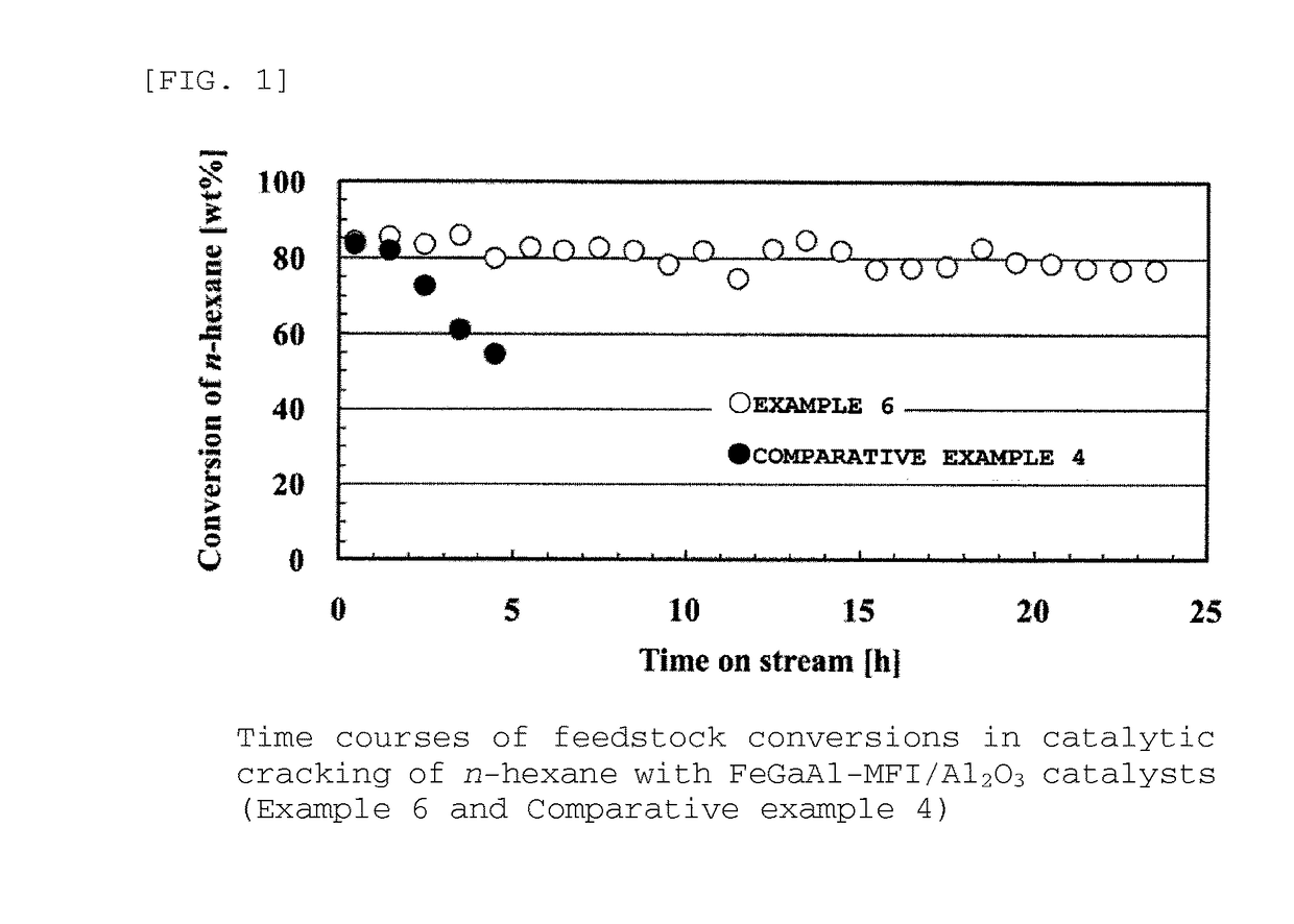
example 6

[0161]It is described below how to prepare a FeGaAl-MFI zeolite (Si / (Fe+Ga+Al)=12.0) / alumina composite in Example 6.

[0162]Na-type FeAl-MFI zeolite was synthesized in the same manner as in Example 1, except that a solution composed of 58.9 g of colloidal silica (30.6 wt % of SiO2, 0.4 wt % of Na2O, and 69.0 wt % of H2O) and 3.98 g of sodium hydroxide was used instead as the liquid A and that a solution composed of 2.54 g of aluminum sulfate n-hydrate, 1.46 g of gallium nitrate n-hydrate, 3.26 g of iron nitrate 9-hydrate, 15.49 g of tetrapropylammonium bromide, and 185.1 g of water was used instead as the liquid B.

[0163]In addition, the resultant powdery Na-type FeGaAl-MFI zeolite and alumina powder were used and molded in the same way as in Example 4, so that a cylindrical FeGaAl-MFI zeolite / alumina composite was obtained. The composite was then subjected to ion-exchange to prepare a FeGaAl-MFI zeolite / alumina composite catalyst.

[0164]The ion-exchange was performed in the same way as...

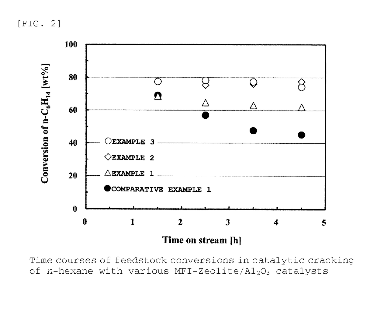
example 1

[0230]It is described below how to synthesize FeGaAl-MFI zeolite (Si / (Fe+Ga+Al)=92.9 (acid density)) in Example 1.

[0231]Liquids A and B were prepared, in which the liquid A was a solution composed of 58.9 g of colloidal silica (30.6 wt % of SiO2, 0.4 wt % of Na2O, and 69.0 wt % of H2O) and 1.76 g of sodium hydroxide, and the liquid B was a solution composed of 0.25 g of aluminum sulfate n-hydrate, 0.15 g of gallium nitrate n-hydrate, 0.33 g of iron nitrate 9-hydrate, 4.13 g of tetrapropylammonium bromide, and 187.8 g of purified water. The liquids A and B were gradually mixed by stirring at room temperature, and the mixture was then further vigorously stirred for 15 minutes in a mixer.

[0232]The mixture solution was allowed to stand overnight while its temperature was kept at 60° C. Subsequently, the mixture solution was subjected to a hydrothermal synthesis reaction at its own pressure in an autoclave under the conditions of 150° C., 72 hours, and 300 rpm.

[0233]After cooled, the pro...


PUM

PropertyMeasurementUnit
boiling pointsaaaaaaaaaa
sizesaaaaaaaaaa

Abstract

Provided are zeolite catalysts that allow reactions to proceed at temperatures as low as possible when lower olefins are produced from hydrocarbon feedstocks with low boiling points such as light naphtha, make it possible to make propylene yield higher than ethylene yield in the production of lower olefins, and have long lifetime. The zeolite catalysts are used in the production of lower olefins from hydrocarbon feedstocks with low boiling points such as light naphtha. The zeolite catalysts are MFI-type crystalline aluminosilicates containing iron atoms and have molar ratios of iron atoms to total moles of iron atoms and aluminum atoms in the range from 0.4 to 0.7. The use of the zeolite catalysts make it possible to increase propylene yield, to lower reaction temperatures, and to extend catalyst lifetime.

Description

TECHNICAL FIELD[0001]The present invention relates to zeolite catalysts for producing lower olefins from hydrocarbons with low boiling points such as light naphtha. The invention also relates to methods for producing these zeolite catalysts and to methods for producing lower olefins with these zeolite catalysts.BACKGROUND ART[0002]Lower olefins (e.g., ethylene and propylene) are important basic raw materials in the petrochemical industries and demand for lower olefins is expected to be steadily increased in the coming years. At present, lower olefins have been produced mainly by steam cracking of naphtha. However, this process, which is non-catalytic, requires high temperatures between 800° C. and 900° C. for cracking, resulting in a large amount of energy consumption.[0003]In this technique, the main product is ethylene, while propylene is a by-product (the gravimetric ratios of ethylene to propylene are ca. 2.0). Therefore, propylene supply by this technique might be insufficient ...

Claims


Application Information

Patent Timeline
Patent Type & Authority Applications(United States)
IPC IPC(8): B01J29/46B01J37/00B01J37/10C10G11/05B01J35/00
CPCB01J29/46C10G11/05B01J37/0009B01J2229/186C10G2400/20B01J2229/18B01J37/10B01J29/87B01J2229/42B01J29/40B01J2229/20C01B39/36C01B39/065C07C4/06C07C2529/88B01J29/88Y02P20/52B01J35/40C07C11/06B01J37/00B01J37/30C10G35/095B01J29/405C07C2529/89C07C2529/42C01B39/46
Inventor HODOSHIMA, SHINYAYAGI, FUYUKIMOTOMIYA, AZUSAWAKAMATSU, SHUHEIASAOKA, SACHIO
Owner CHIYODA CORP
Learn More