Eureka AIR delivers breakthrough ideas for toughest innovation challenges, trusted by R&D personnel around the world.

Shield-carried noncontact frequency-domain electrical real-time advanced detection system and method

Active Publication Date: 2017-10-26
SHANDONG UNIV
View PDF0 Cites 5 Cited by
  • Summary
  • Abstract
  • Description
  • Claims
  • Application Information

AI Technical Summary

Benefits of technology

The present invention is a system and method for detecting objects using a shield-carried machine. It uses noncontact electrodes on the machine to detect objects by measuring their capacitance. The data is then sent to a control system and translated in real-time. The system helps to predict and avoid potential hazards, supporting the safety construction of the shield tunneling machine.

Problems solved by technology

The earth pressure balance shield construction belongs to full-section tunnel boring machine construction and is mainly used for urban underground soft soil ground layer construction, and the bad geological condition is more complex due to shallow burying and abrupt changes of geological units.
Meanwhile, since urban ground buildings are dense, it is difficult to comprehensively find out the bad geological condition along the subway line by ground investigation.
Once bad geological bodies such as water rich quick sand layers, water-containing corrosion cavities, boulders and the like are encountered in the excavation process, and engineering accidents such as collapse, water outburst, ground surface settlement and the like often happen, situations are caused ranging from damage of shied machinery and construction period delay to stratum collapse resulting in major safety accidents.
However, the whole space of a shield construction tunnel is occupied by a huge shield tunneling machine, no detection space is available for geophysical detection, meanwhile, the construction vibration of shield machinery, huge metal bodies, supporting mechanical and electrical equipment and the like seriously interfere with geophysical fields such as an electric field, a wave field and the like, as a result, common geophysical prospecting methods such as a seismic wave method, an electromagnetic method and the like for a drilling and blasting method are inapplicable.
Meanwhile, positioning of BEAM excessively depends on experience, so that the positioning precision is low and three-dimensional imaging cannot be realized.
(1) An earth pressure balance shield cutter head closely clings to the earth of the tunnel face all the time and cannot be retracted in order to keep the earth pressure balance of the tunnel face in the construction environment of the shield tunneling machine, so no detection space is available in front of the cutter head, and an observation mode or method available in front of the shield cutter head is the first problem to be solved.
(2) Common electrical detection adopts contact electrodes in contact coupling with the tunnel face. The electrodes and the propulsion device exposed in front of the cutter head are easily influenced by the tunneling construction and easily damaged, and it is difficult for the contact electrodes to work under the rotation of the cutter head, so how to adopt the noncontact electrodes to realize real-time advanced detection in the rotating mode of the cutter head is an important problem. In addition, the problem about a rotary junction device and an electrode positioning device also needs to be solved in order to realize real-time detection of the shield.
(3) Since noncontact electrodes are adopted, current emission and reception instruments required for frequency-domain electrical detection also need to be developed, meanwhile, in order to meet the requirement for quick construction of the shield, how to realize real-time automatic detection of a detection system is a further problem, and a system for controlling current emission, signal acquisition, electrode positioning and quick interpretation is needed.

Method used


Image

  • Shield-carried noncontact frequency-domain electrical real-time advanced detection system and method
  • Shield-carried noncontact frequency-domain electrical real-time advanced detection system and method
  • Shield-carried noncontact frequency-domain electrical real-time advanced detection system and method

Examples


Embodiment Construction

[0061]The present invention will be further described below in combination with the accompanying drawings and embodiments.

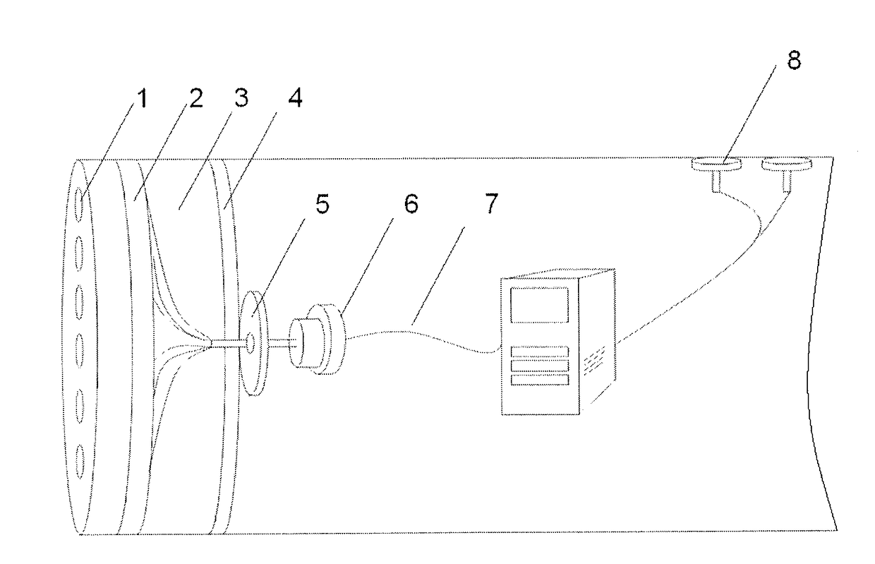
[0062]As shown in FIG. 1, a noncontact frequency-domain electrical real-time advanced detection system includes noncontact electrodes 1, an electrode positioning device 5, a power supply and measurement device and a host system 32; the noncontact electrodes 1 are arranged on a front panel of a cutter head, and each noncontact electrode 1 is converged to a multi-core cable 7 via a swivel joint by a single-core cable and then connected to the power supply and measurement device.

[0063]The swivel joint 6 is installed in the middle of the cutter head, the electrode positioning device 5 is only installed in the middle of the cutter head and is hollow, and the single-core cables for connecting the electrodes can penetrate through the electrode positioning device 5. The electrode positioning device 5 is only electrically connected with the host system 32.

[0064]The electr...


PUM


Abstract

A shield-carried noncontact frequency-domain electrical real-time advanced detection system and method. Noncontact electrodes are installed on a cutter head of a shield tunneling machine, current is emitted and received using capacitance coupling, the electrodes are connected to a host via a multi-way swivel joint, measured data is inversed and interpreted in real time, and the prediction result is transmitted to a control system of the shield tunneling machine so as to provide a technical support for safety construction of the shield tunneling machine; the noncontact electrodes are installed on the shield cutter head. Real-time advanced detection of geology in front of a tunnel face can be realized in the tunneling process, so that the requirement for quick tunneling construction is met, and the efficiency of advanced geological detection of the shield tunneling machine is improved; and an electrode system is only installed on the cutter head.

Description

FIELD OF THE INVENTION[0001]The present invention relates to a shield-carried noncontact frequency-domain electrical real-time advanced detection system and method.BACKGROUND OF THE INVENTION[0002]At present, more than 40 counties in the world have opened urban subway lines, and developed counties own highly developed urban subway facilities. Subways have borne a main passenger transportation task in traffic of many cities, and the lives of residents in such cities as Moscow, New York, Beijing and the like is inseparable from the subways. Due to the advantages and convenience of rail transit, more and more countries and cities begin to develop their rail transit. With the rapid development of worldwide rail transit, more and more tunnels will be built in each country in the field of rail transit. Compared with traditional tunnel construction methods such as an open cut method, shallow-buried tunneling method and the like, the shield construction method has the advantages of “high tu...

Claims


Application Information

Patent Timeline
IPC IPC(8): E21D9/00E21D9/06
CPCE21D9/003E21D9/0692E21D9/0621G01V3/06G08C15/10E21D9/004G01V3/08G08C23/04G01V3/26
Inventor LI, SHUCAINIE, LICHAOLIU, BINLIU, HAIDONGREN, YUXIAOSONG, JIELIU, ZHENGYUGUO, QIANWANG, CHUANWU
Owner SHANDONG UNIV
Why Eureka
Eureka Blog
Learn More