Porous carbon electrodes for energy storage applications

a technology of porous carbon electrodes and energy storage applications, which is applied in the direction of carbon compounds, inorganic chemistry, chemistry apparatus and processes, etc., can solve the problems of curtailing widespread application and shortening energy-density capabilities, and achieve linear increase in capacitance, high surface area, and high surface area

Active Publication Date: 2017-11-09
FARAD POWER
View PDF0 Cites 5 Cited by
  • Summary
  • Abstract
  • Description
  • Claims
  • Application Information

AI Technical Summary

Benefits of technology

[0032]Several problems associated with pore size and distribution of existing EDLC electrodes drive the search for new electrode manufacturing techniques. For example, higher surface area not always better. Although activated carbon with very high surface area (>3500 m2 / g) is commercially viable, electrodes made with these carbons rarely show a linear increase in capacitance with increasing surface area. This is often attributed to the inability of the electrolyte ions to access the small pores, which are the significant contributor to the high surface area of carbon electrode. Another unintended consequence of the smaller and smaller pore sizes is low stability under high voltage operations. As the surface area increases, the number of small pores increases resulting in a decrease in the pore wall thickness, making the EDLC susceptible to failure in the presence of high electric fields. Porosity in the current EDLC electrodes is obtained from the inherent porosity in the coconut-shell carbon these electrodes are made from, and from the activation process of the carbon (via heating at high temperatures under steam or CO2).
[0033]Further, for organic electrolyte-based devices, two types of pores are preferable as shown in FIG. 2. These are: 1) a “micro”-pore distribution of ˜2 nm and above, which can support the double-layer formation without overcrowding the ions; 2) and a set of transport pores with diameter 10-20 nm and higher, which acts as a reservoir for the electrolyte during the charge-discharge process.
[0034]In addition, the so-called “tortuous pores” (as opposed to “straight” pores) that are typically obtained with the current activation processes used to create porous carbon electrodes today are known to reduce the conductivity of the electrolyte in the device and also to hinder the double-layer formation (Kotz, R. and Carlen M., Electrochimica Acta, 2000, 45:2483-2498; and DeLaRue, R. E. and Tobias, C. W., J. Electrochem. Soc., 1959, 106:827). The more desirable configuration is “straight” pores for transport that also allow the use of thicker electrodes (up to 200 um), without requiring any conductivity enhancers. The use of thicker electrodes also increases the volumetric capacitance resulting in better energy densities of the final device by reducing the amount of aluminum foil (several times as dense as the carbon electrode itself) that is currently used as the current collector in existing configurations.
[0035]Further, in one of the final steps in current device manufacturing, the porous electrodes are dried before being filled with the electrolyte. In the case of high surface-area porous carbon with very small pores (typically <2 nm), water removal is a tedious and expensive process. However, since even trace amounts of water in the micro-pores reduces the overall cycle life of the device (by generating a series of Faradic reactions), drying the electrode is a very critical step. Newer porous electrode manufacturing processes thus focus on creating >2 nm pores for the double-layer formation and try to eliminate any <2 nm pores because these cannot support double-layer formation, but at the same time keep tightly held water molecules from being driven out during the drying process. Other studies have shown that pores <1.8 nm do not participate in double-layer formation (Barbieri, O. et al., Carbon, 2005, 43:1303).
[0036]The templating techniques of the present invention are fundamentally different from the techniques currently used and can address all the points made above with respect to improving the overall performance of supercapacitor devices. Our fundamental process utilizes a polymerization reaction of various carbon sources to form a solid carbon material with either a “hard” (external) template or a “soft” (internal) template, or both. The carbon source is polymerized in the presence of catalysts selected according to the type of polymerization reaction undergone by the carbon source. Besides the hard and soft templates used to form pores, our method is also compatible with the standard activation processes used today to create pores, although they are not required, and if used, need to be controlled to prevent the issues described above.
[0037]Production of Nano-Porous Carbon. The starting materials (carbon sources) utilized in the method of the present invention are liquid and can be classified in to two categories. Class 1 materials undergo very fast polymerization reactions. Class 1 carbon-containing sources comprise the furfuryl moiety compound and its fast-polymerizing derivatives, including, but not limited to, furfuryl alcohol, acetylfuran, furfuraldehyde, 5-hydroxymethylfurfural and 5-methlyifurfural. Furfuryl alcohol and some of its derivatives polymerize very quickly in the presence of the some catalysts (mentioned below) (Gonzalez, R. et al., Makromol. Chem., 1992, 193:1-9). This reaction needs to be controlled by either using milder catalysts (e.g. solid alumina, Al2O3, or aluminum hydroxide, Al(OH)3) or by diluting the furfuryl alcohol with a less reactive liquid carbonyl-containing carbon source, for example, acetone and reducing the reaction temperature if catalysts like silane or TiCl4 (or their derivatives) are used. In the former case (Class 1 sources plus solid alumina or aluminum hydroxide powder), a hard template is formed by the ceramic powder, while in the latter case (Class 1 sources plus silane or TiCl4 catalysts), an internal “soft” template of either Si-O or Ti—O links remain embedded in the solid carbon.

Problems solved by technology

However, they have fallen short in energy-density capabilities, which has curtailed their widespread application as an alternative, more powerful energy source to conventional batteries.

Method used


Image

  • Porous carbon electrodes for energy storage applications
  • Porous carbon electrodes for energy storage applications
  • Porous carbon electrodes for energy storage applications

Examples


example 1

Polymerization of Furfuryl Alcohol Using Alumina

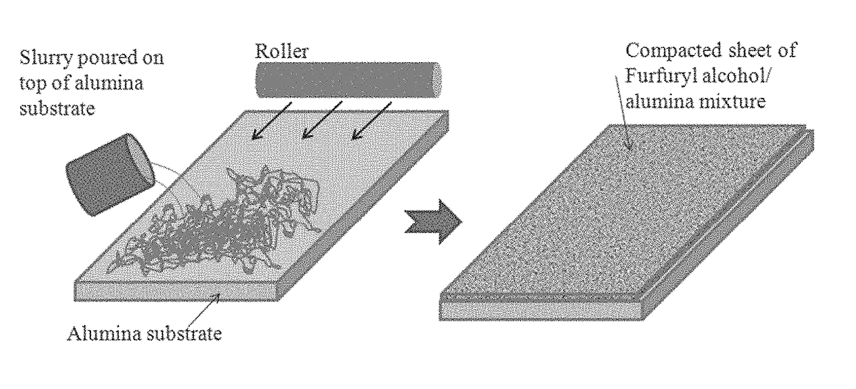
[0056]Formation of Porous Carbon Matrix. Three sizes of alumina or Al(OH)3 particles were used as catalyst templates for the polymerization of furfuryl alcohol. The amounts of alumina and furfuryl are given in Table I. In a one-liter beaker, the furfuryl alcohol (Sigma-Aldrich, St. Louis, Mo.) (See FIG. 14, A) was stirred using a magnetic stirrer while the Al(OH)3 powder was added slowly (FIG. 14, B). The stirring continued until the mixture was thick and no more powder could be added (FIG. 14, C). The mixture was then subjected to ultrasonic vibration to increase mixing, by lowering the beaker into a water bath and then ultrasonically vibrating for up to 30 minutes. The mixture was transferred to a 500-mL (16 oz.) glass jar. The mouth of the jar was covered with Teflon tape before the jar cap was screwed on. The mixture was allowed to stand at room temperature for about two days as the polymerization process started as signified by a ...

example 2

Polymerization of 2-Acetylfuran Using Dichlorodimethylsilane

[0060]In a one-liter beaker, 100 g of 2-acetylfuran (Sigma-Aldrich) was stirred for a few minutes using a magnetic stirrer. Catalyst dichlorodimethylsilane, Si(CH3)2Cl2 (25 mL) (Sigma-Aldrich), was added slowly. Stirring was continued for 5 minutes and the stir bar was then removed. The mixture was transferred to a 500-mL (16 oz.) glass jar. The mouth of the jar was covered with Teflon tape before the jar cap was screwed on. The jar was allowed to stand at room temperature for 190 hours. A black solid formed.

example 3

Polymerization of Furfuryl Alcohol Using Dichlorodimethylsilane

[0061]In a one-liter beaker, 150 mL of furfuryl alcohol (Sigma-Aldrich) along with 125 mL acetone (high purity, HPLC grade) was stirred for a few minutes using a magnetic stirrer. NaOH pellets (0.1 g) were then added to the mixture and dry ice was packed around the beaker to cool it down. Catalyst dichlorodimethylsilane, Si(CH3)2Cl2 (30 mL) (Sigma-Aldrich), was added slowly. Stirring was continued. A black solid formed.

[0062]The polymerized material was then heated to 600° C. over a period of one hour in a vacuum tube furnace (Model #GSL-1100, MTI Corporation, Richmond, California, US), for under a controlled nitrogen atmosphere. The furnace was maintained at 600° C. for one hour, then allowed to cool naturally to room temperature. The polymerized materials were loaded into quartz boats that were then placed in the center of the quartz tube. Gas lines were attached to one side of the tube using the vacuum fittings provid...


PUM

PropertyMeasurementUnit
temperatureaaaaaaaaaa
sizeaaaaaaaaaa

Abstract

The present patent application discloses a method of producing nano-porous carbon, comprising mixing furfuryl alcohol or its fast-polymerizing derivatives with an aluminum-based solid polymerization catalyst, heating the mixture until a solid catalyst-carbon matrix forms, heating again under inert atmosphere and etching the powder to remove the matrix to produce a network of pores in the nano-porous carbon. The application further provides a method for making of fabricating tailor-made nano-porous carbon electrodes.

Description

CROSS-REFERENCE TO RELATED APPLICATIONS[0001]This application claims the benefit of Indian Patent Application 201617015427 filed on May 2016, the contents of which are incorporated in their entirety.BACKGROUND OF THE INVENTION[0002]Electrical double layer capacitors (EDLCs), also called supercapacitors or ultracapacitors, have received a lot of interest lately due to their potential for providing high power densities. However, they have fallen short in energy-density capabilities, which has curtailed their widespread application as an alternative, more powerful energy source to conventional batteries. Commercially available supercapacitors today are constructed from activated carbon electrodes made primarily from coconut-shell charcoal powder and have surface areas of 2000 m2 / g and energy densities of ˜6 Wh / Kg (Pandolfo, A. G. et al., J. Power Sources, 2006, 157:11-27; Conway, B. E. et al., Electrochemical Supercapacitors: Scientific Fundamentals and Technological Applications, 1999...

Claims


Application Information

Patent Timeline
Patent Type & Authority Applications(United States)
IPC IPC(8): H01G11/86H01G11/36H01G11/34H01G11/42H01G11/24
CPCH01G11/86C01B31/086H01G11/42H01G11/34H01G11/36H01G11/24H01G11/44C01B32/366
Inventor MITRA, SHANTANU
Owner FARAD POWER
Why Eureka
Try Eureka