Low-pressure drop structure of particle adsorbent bed for adsorption gas separation process

a gas separation and low-pressure drop technology, applied in the direction of inorganic chemistry, lighting and heating apparatus, alkali metal oxides/hydroxides, etc., can solve the problems of large, limited mass transfer rate achievable, large residence time, etc., to optimize thermal conductivity of heat transfer structure, optimize thermal mass/heat, and reduce the effect of gas flow

Active Publication Date: 2017-11-16
CLIMEWORKS
View PDF4 Cites 19 Cited by
  • Summary
  • Abstract
  • Description
  • Claims
  • Application Information

AI Technical Summary

Benefits of technology

[0020]Further prior art devices (e.g. WO2010 / 027929 A1, U.S. Pat. No. 8,202,350 B2) utilize structures in which the gas flow can be guided through layers of porous sorbent materials but these structures are based on extruded monolithic structures which are essentially 2-dimensional structures extruded in a third dimension. In these structures, the sorbent material is in a monolithic structure, e.g., in a gel form or deposited on the channel walls, so it is not loose. Further, the structures are typically extruded from a single material and the extrusion process does not allow combination of arbitrary materials to build up the structures. There are several advantages of the structures of the present invention over prior art extruded monolithic structures.
[0021]Firstly, structures based on extruded monoliths cannot represent more complex 3-dimensional structures such as a stack of individual layers with loose particular sorbent material confined by flexible fabric sheets. This in turn means that the prior art structures cannot represent the geometries of the structures of the present invention, for example a heat transfer structure connected to tubing and being embedded into a sorbent material layer enclosed between two layers of a fabric material (see below).
[0022]Secondly, the prior art structures cannot be easily built up from various different material combinations, as the structures of the present invention, with the corresponding advantages listed in detail below, such as optimized thermal mass / heat capacity, optimized thermal conductivity of a heat transfer structure, etc. In particular, incorporation of a flexible fabric material enclosing the sorbent layers, in contrast to prior art, allows for (i) using flexible and to a certain extend stretchable fabric sheets holding the sorbent material in the shape of a thin, uniform layer, even if the volume of the particle layer shrinks or expands to some extend during operation (e.g., through drying and wetting of the material); and (ii) tailoring the fabric sheets to be just impermeable to the sorbent material particles but at the same time to be very thin and impose a very low pressure drop on the gas flow through them. In contrast, fixed, stiff channels walls of prior art monolithic structures (i) cannot adapt to a shrinking and / or expanding sorbent packing, and (ii) will typically either be thicker or have less porosity for the gas flow to pass through than optimized flexible fabric sheets since the former will require a more dense structure in order to maintain their stiff structure.
[0023]Thirdly, prior art monolithic structures are likely to be subject to a significant amount of flow by-passing the layers of sorbent material, leading to a reduced mass transfer rate during the adsorption process. This is due to the fact that at those locations at which sorbent material is in contact with rigid structures such as the walls of the monolith, small cavities in the sorbent material are likely to form (for example during the filling or coating process), which reduce the resistance on the air flow at these locations and in turn induce a by-pass flow through them. In the structure of the present invention, the number of walls inside the packing of the sorbent material can be kept substantially smaller compared to prior art monolithic structures.
[0024]Fourthly, the proposed use of loose particulate adsorption material in combination with flexible fabric for bordering the layers and in combination with the stacked arrangement with specifically chosen layer thicknesses and channel widths allows providing for a very robust, low-pressure drop, easy to handle and low manufacturing cost device with high efficiency of the adsorption and desorption process, where its geometry can be specifically tailored to the process-specific needs. This is in contrast to monolithic structures where the sorbent material is provided not in loose form but in a solidified porous monolithic form, which structures are much more restricted through the manufacturing process, and, due to the fixed local arrangement of the sorbent material in the channels or at their walls, respectively, do not allow for easy manufacturing, easy cleaning, repowering etc. In particular, the stacked unit of the present invention can be substantially arbitrarily extended into one direction perpendicular to the main direction of the gas flow (which is, the direction of stacking) without complicating the manufacturing process. This is in contrast to a prior art extruded monolithic structure, which requires larger die-plates if the dimensions perpendicular to the main direction of the gas flow are enlarged.
[0025]Moreover, there can be further advantages of the structure of the present invention over prior art extruded monolithic structures due to the above listed fundamental differences in their construction.

Problems solved by technology

However, such a bed arranged in a single layer would result in very large, technically and economically unfeasible geometries of the overall sorption system.
However, if species are to be removed from the gas stream at very low concentrations (such as CO2 in air) the concentration gradients from the gas stream to the sorbent bed are small which limits the achievable mass transfer rates and requires long residence times, which in turn can render the process uneconomical.

Method used


Image

  • Low-pressure drop structure of particle adsorbent bed for adsorption gas separation process
  • Low-pressure drop structure of particle adsorbent bed for adsorption gas separation process
  • Low-pressure drop structure of particle adsorbent bed for adsorption gas separation process

Examples


example 1

Working Example of the Present Invention in the Form of a Rectangular Stack

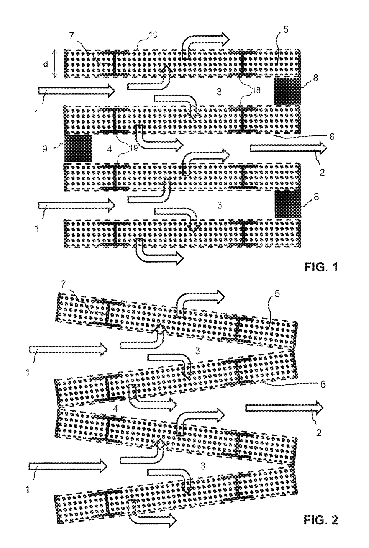
[0118]According to one working example, the structure is composed of rectangular layers of sorbent material stacked on top of each other to form a rectangular block shaped stack comprising inlet channels, outlet channels and the sorbent layers. In this example, the fabrication and assembly of this example is described to illustrate the applicability of this invention in the form of a useful product for CO2 extraction from ambient air.

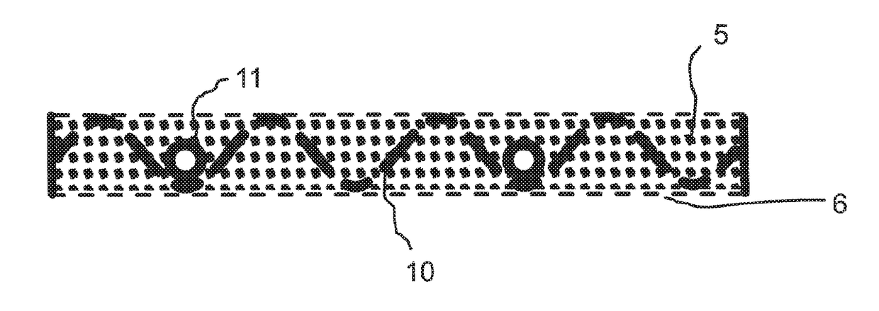
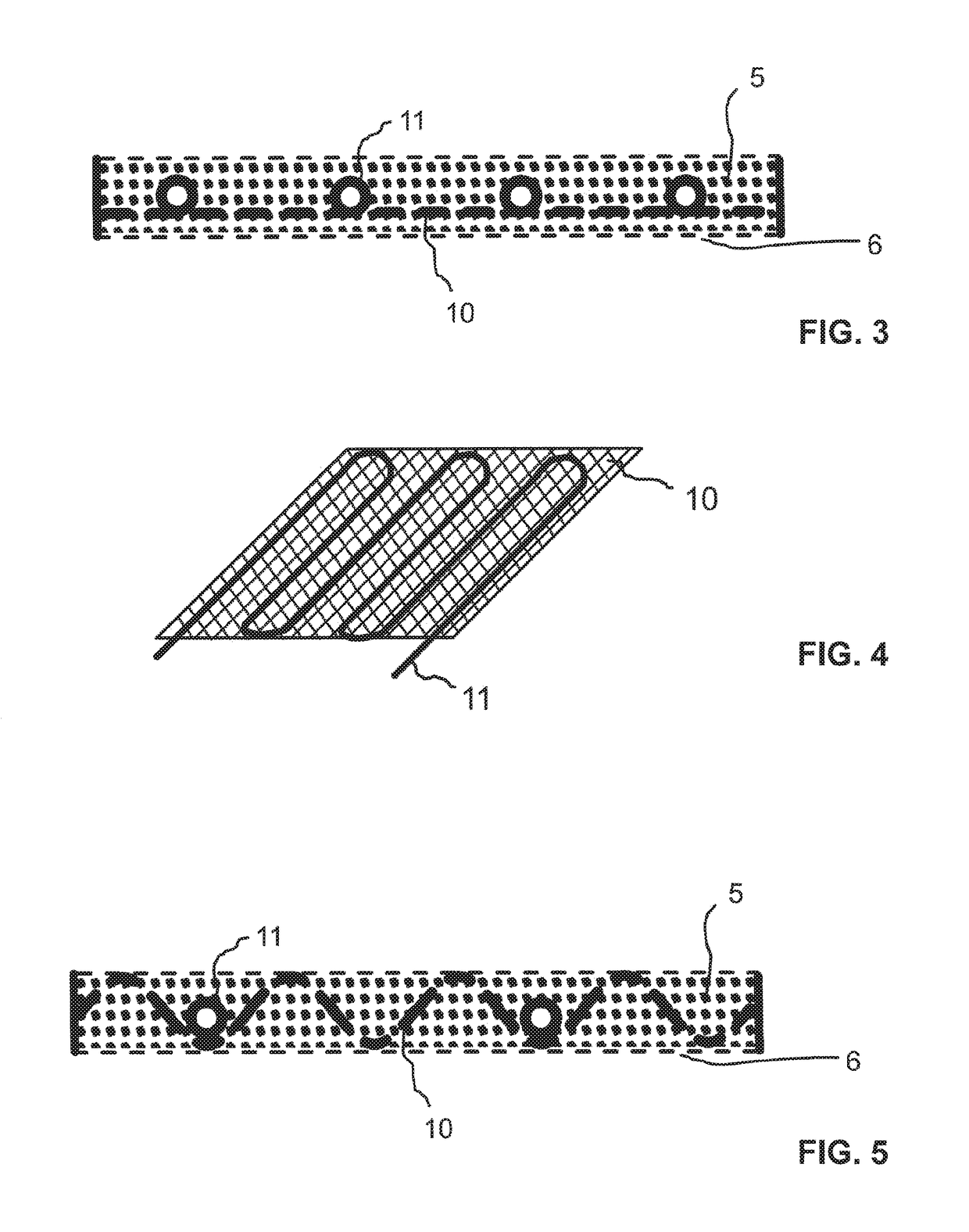
[0119]The individual sorbent material layers are formed by stiff frame structures, each comprising a rectangular frame with 0.5 m×0.6 m edge length and a height of 1 cm, made of stainless steel profiles. A top-view of such a single frame is shown in FIG. 10, a respective cross section in FIG. 11. The fabrication and assembly of the overall structure comprises the following steps:[0120]1. The frame structures are fabricated by welding stainless steel profiles (e.g. for high-volume...

example 2

Determination of the Pressure Drop Through a Stack of Sorbent Layers

[0140]The pressure drop imposed on an air flow passing through a structure essentially fabricated according to the description of Example 1 is experimentally determined for different flow rates. To this end, both butterfly valves are opened and a variable speed fan is attached to the inlet opening producing different air flow rates through the stack. The flow rate is measured with an in-pipe velocity head meter and the pressure drop over the structure is measured using a differential pressure sensor. The observed pressure drop for various volume flow rates is shown in the following table:

Volume flow (m3 / h)Pressure drop (Pa)20016400316005880098

[0141]It is found that up to the design flow rate of 800 m3 / h, which is required to capture around 1 kg of CO2 from air per cycle (see Example 3), the pressure drop stays below 100 Pa. If the average pressure drop during the adsorption process is 100 Pa, the required pumping wo...

example 3

Performance of Example 1 within a Cyclic Adsorption / Desorption Process

[0143]A structure essentially fabricated according to the description of Example 1 is used for a cyclic temperature-vacuum swing adsorption / desorption process to extract CO2 from ambient air. One cycle of the process takes about 6 hours and comprises the steps adsorption (3 hours) and desorption (3 hours).

[0144]During the adsorption step, according to Example 2 above, the butterfly valves are opened and air is blown through the structure by a variable speed fan, while the flow rate is recorded. Further, the CO2 content of the air flow and its relative humidity are measured before and after the vacuum chamber using an infrared detector. The relative humidity during the adsorption process is relatively constant between 35% and 40%. The air flow is 750 to 800 m3 / h. The CO2 concentration before and after the chamber (“adsorption breakthrough curves”) during adsorption are shown in FIG. 10.

[0145]It is surprisingly foun...


PUM

PropertyMeasurementUnit
relative inclination anglesaaaaaaaaaa
particle diameteraaaaaaaaaa
diameteraaaaaaaaaa

Abstract

A gas separation unit for the separation of carbon dioxide from air is proposed for use in a cyclic adsorption/desorption process and using a loose particulate sorbent material. Sorbent material is arranged in at least two stacked layers, and each layer comprises two sheets of a flexible fabric material which is gas permeable but impermeable to the loose sorbent material. The sheets are arranged parallel defining an inlet face and an outlet face, are arranged with a distance in the range of 0.5-2.5 cm, and are enclosing a cavity in which the sorbent material is located. Said layers are arranged in the unit such that the inflow passes through the inlet face, subsequently through the particular sorbent material located in the cavity of the respective layer, subsequently to exit the layer through the outlet face to form the gas outflow.

Description

[0001]THIS APPLICATION IS A CONTINUATION-IN-PART OF U.S. APPLICATION SER. NO. 14 / 785.152 FILED OCT. 16, 2015 WHICH IS A NATIONAL STAGE OF INTERNATIONAL APPLICATION NO. PCT / EP2014 / 057185 FILED APR. 9, 2014, CLAIMING PRIORITY BASED ON EUROPEAN PATENT APPLICATION SER. NO. 13 164 230.8, FILED APR. 18, 2013, THE CONTENTS OF ALL OF WHICH ARE INCORPORATED HEREIN BY REFERENCE IN THEIR ENTIRETY.TECHNICAL FIELD[0002]The present invention relates to sorbent bed structures for gas separation processes and the use of such structures for gas separation, for example for the separation / capture of CO2 from gas streams.PRIOR ART[0003]Gas separation by adsorption has many different applications in industry, for example removing a specific component from a gas stream, where the desired product can either be the component removed from the stream, the remaining depleted stream, or both. Thereby both, trace components as well as major components of the gas stream can be targeted by the adsorption process....

Claims


Application Information

Patent Timeline
Patent Type & Authority Applications(United States)
IPC IPC(8): B01D53/04B01J20/24B01J20/28F28F9/26F28F1/32F28F1/12
CPCB01D53/0415F28F9/26F28F1/126F28F1/32B01D53/0462B01D53/0438B01J20/24B01J20/28023B01J20/28004B01J20/28052F28F2255/12B01D2253/25B01D2253/20B01D2257/504B01D53/0407B01D2253/34B01D2258/0283B01D2258/06Y02C20/40B01D53/0454B01D2258/02
Inventor GEBALD, CHRISTOPHPIATKOWSKI, NICOLASRUESCH, TOBIASWURZBACHER, JAN ANDRE ANDRE
Owner CLIMEWORKS
Why Eureka
Try Eureka