


Quick Research
Generate reliable direction feasibility study reports for your R&D in just a few steps.

Technical Q&A
Discover and master advanced knowledge NOW. Basics, ideas, possibilities, all at once.

Find Solutions
As an expert in R&D theories, this can generate solutions to your technical problems instantly.

Evaluate Feasibility
Analyze your overall solution with one click, know your potential R&D risks in advance.

Monitor Landscape
Get weekly tech updates, stay abreast of the latest tech innovations and key insights.
Zinc electrodes for batteries
- Summary
- Abstract
- Description
- Claims
- Application Information
AI Technical Summary
Benefits of technology
Problems solved by technology
Method used
Image

Examples
example 1
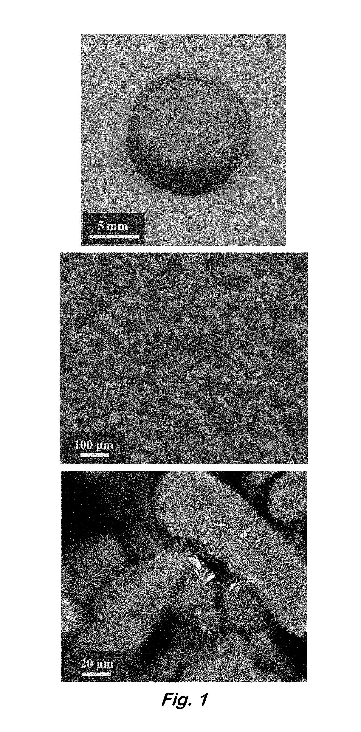
[0039]Fabrication of Monolithic Zinc Sponges—
[0040]A typical preparation of zinc sponge electrodes begins with the formation of an emulsion of zinc powder in water and decane. In a small beaker or scintillation vial, 6.0 g of zinc powder that also contains 300-ppm indium and 285-ppm bismuth (as-received from Grillo-Werke AG) was added. The indium and bismuth additives are necessary to raise the overpotential for hydrogen evolution in alkaline electrolytes, while eliminating the need for toxic additives such as lead and mercury (Glaeser, U.S. Pat. No. 5,240,793). Water (1.027 mL) and decane (2.282 mL) were added along with an emulsifier, sodium dodecyl sulfate (6.3 mg) and emulsion stabilizer, carboxymethylcellulose (0.253 g). The use of these ingredients in the formation of zinc emulsions that are subsequently used to make zinc electrodes has been described previously (Drillet et al., “Development of a Novel Zinc / Air Fuel Cell with a Zn Foam Anode, a PVA / KOH Membrane, and a MnO2 / SiO...
example 2
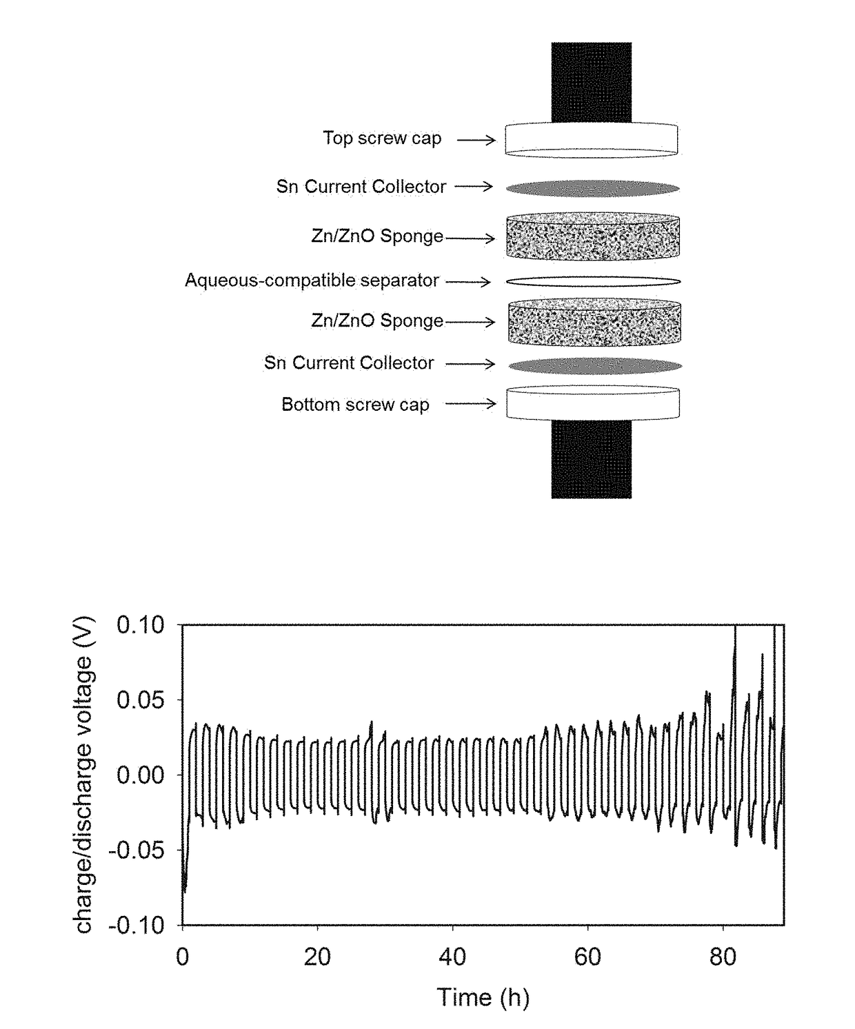
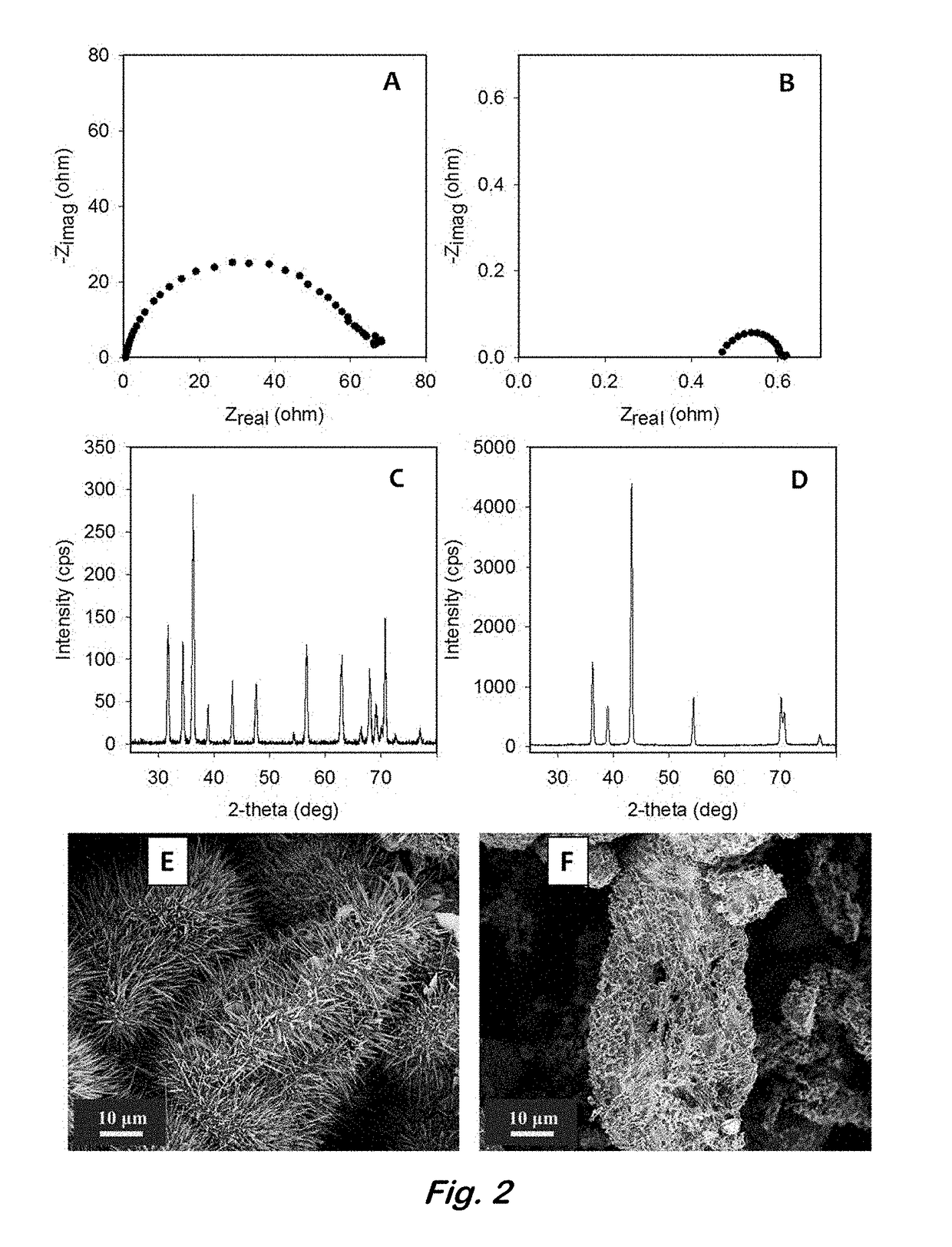
[0045]Reversibility of Zinc Sponge Anodes—
[0046]In order to study the reversibility of the 3D zinc sponge in a battery configuration, without the requirement of having an optimized cathode (e.g., bifunctionally catalytic for the ORR or OER), a symmetrical electrochemical cell containing an all-metal Zn sponge versus a Zn / ZnO sponge separated by an aqueous-compatible separator was used. The Zn / ZnO sponge was prepared by electroreducing some of the ZnO present from the post-heated sponge by applying −50 mV versus zinc for 10-min increments. The EIS and the OCP were measured after each cycle. The reduction of this sponge was terminated when the RCT in the EIS fell below 0.5 Ωcm−2, but the OCP remained greater than 30 mV vs. Zn, indicating high conductivity throughout the sponge network, yet ZnO remained. A second post-heated sponge was reduced at −50 mV versus Zn for 30-min increments as described in [0032] until it was fully reduced to an all metal Zn sponge with an OCP very close to ...
example 3
[0047]Zinc Sponges as a Negative Electrode in Rechargeable Nickel-Zinc Batteries—
[0048]Following the electrochemical reduction step to convert a thermally treated Zn sponge to the metallic Zn0 analog, the Zn sponge was thoroughly rinsed with deionized water, dried, and re-weighed in order to get an accurate assessment of Zn active material capacity before prototype testing. The total mass of the ˜1-cm2 reduced Zn sponge used for this example was 0.140 g. Once dried overnight, the Zn sponge was vacuum-infiltrated with a water-based slurry of Ca(OH)2 (in this case 0.4 g mLH2O−1), which is known to aid Zn anode rechargeability (U.S. Pat. No. 5,863,676). The Ca(OH)2-infused Zn sponge was removed from the Ca(OH)2 slurry and gently rinsed with water to remove excess Ca(OH)2, dried overnight in vacuo, and re-weighed to yield a Zn sponge infused with, as an example, ˜6 wt. % Ca(OH)2. The dried electrode was then infiltrated with the electrolyte that comprises 6 M KOH and 1 M LiOH, the latte...
PUM
 Abstract
Description
Claims
Application Information
 - R&D Engineer
- R&D Manager
- IP Professional
- Industry Leading Data Capabilities
- Powerful AI technology
- Patent DNA Extraction
Browse by: Latest US Patents, China's latest patents, Technical Efficacy Thesaurus, Application Domain, Technology Topic, Popular Technical Reports.
© 2024 PatSnap. All rights reserved.Legal|Privacy policy|Modern Slavery Act Transparency Statement|Sitemap|About US| Contact US: help@patsnap.com