Laser apparatus and manufacturing method thereof

a technology of laser equipment and manufacturing method, which is applied in the direction of laser details, active medium materials, laser cooling arrangements, etc., can solve the problems of reducing the light emission performance of the laser medium, reducing the intensity of the laser beam that can be outputted from the laser medium, and not being able to increase the laser beam intensity to the required level, etc., to achieve the effect of reducing the length of the resonan

Inactive Publication Date: 2017-12-14
INTER UNIV RES INST NAT INST OF NATURAL SCI
View PDF15 Cites 8 Cited by
  • Summary
  • Abstract
  • Description
  • Claims
  • Application Information

AI Technical Summary

Benefits of technology

[0027]According to the technique disclosed herein, since a member through which the excitation beam permeates can be used as the heat sink, the excitation beam, which had reflected in the laser medium and is passing through the transparent heat sink, can be reflected to pass through the transparent beat sink again and be redirected towards the laser medium. Due to this, an excitation beam reflecting mechanism that is configured to reflect the excitation beam, which is passing through the heat sink after having reflected in the laser medium, to redirect the excitation beam to pass through the heat sink towards the laser medium can be employed. Due to this, the resonator length can be shortened.

Problems solved by technology

Studies conducted by the inventors have revealed that the methods (1) to (3) cannot sufficiently cool the laser medium due to thermal resistance being too high between the laser medium and the heat sink.
That is, it has been revealed that an intensity of laser beam that can be outputted from the laser medium cannot be increased to a required level.
According to the method of (4), although the thermal resistance between the laser medium and the heat sink can sufficiently be reduced, strong thermal stress is generated in the laser medium after bonding due to high temperature used in the diffusion bonding and a difference in thermal expansion coefficients of the laser medium and the heat sink, which reduces a light emitting performance of the laser medium, and thus alters an optical property of emitted light to something that was not intended.
There are cases where a length of a laser medium (length along an incident direction of the excitation beam) is short, and the laser medium cannot sufficiently absorb the excitation beam.
In a case of a thin plate-shaped laser medium with a short distance between an input surface of the excitation beam and an output surface of the laser beam, a problem that the laser medium cannot sufficiently absorb the excitation beam may occur.

Method used


Image

  • Laser apparatus and manufacturing method thereof
  • Laser apparatus and manufacturing method thereof
  • Laser apparatus and manufacturing method thereof

Examples


embodiments

First Embodiment: Pulse Laser Apparatus

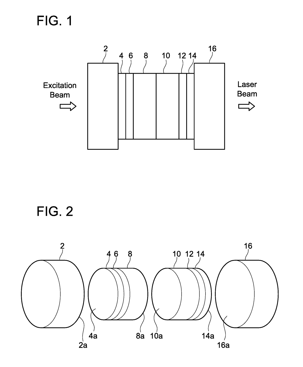
[0059]FIG. 1 shows a side view of a pulse laser apparatus of a first embodiment, and FIG. 2 is a disassembled perspective view thereof. Reference sign 2 shows a first heat sink, reference sign 8 shows a laser medium, reference sign 10 shows a saturable absorber, and reference sign 16 shows a second heat sink. The laser medium 8 emits light when excitation beam enters therein through the first heat sink 2, and pulse laser beam is discharged through the second heat sink 16.

[0060]Reference sign 6 shows a first end coat, having a low reflectance to the excitation beam and a high reflectance to the laser beam. Reference sign 12 shows a second end coat, having an intermediate reflectance to the laser beam. That is, a part of the laser beam is reflected therein and another part of the laser beam permeates therethrough.

[0061]The laser medium 8 emits light when the excitation beam enters therein. The saturable absorber 10 has an absorbing ability that i...

second embodiment

Apparatus

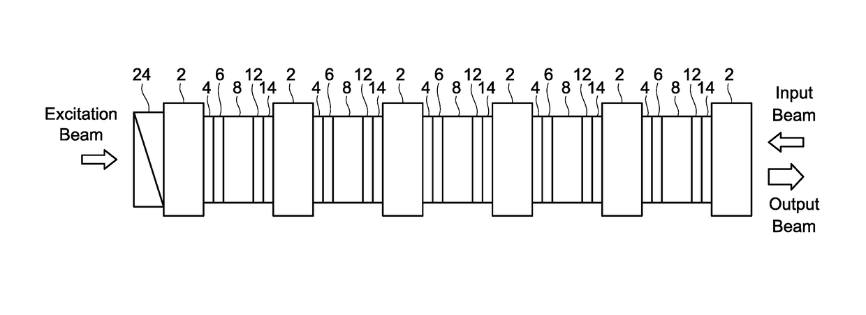
[0073]FIG. 7 shows a multilevel laser apparatus of a second embodiment, which is a multilevel laser amplifier that aligns a plurality of laser media 8 linearly in multiple levels. Each of the laser media 8 emits light when excitation beam and input beam (seed light) enter therein, and amplified laser beam of the input beam is output. Films 6 and 12 adjusted to an intermediate reflectance to laser beam are provided on both surfaces of each laser medium 8.

[0074]A heat sink 2 is inserted between each pair of adjacent laser media 8, 8. The heat sinks 2 have a higher thermal conductivity than the laser media 8, and are configured to allow the excitation beam, the input beam, and the laser beam to permeate therethrough.

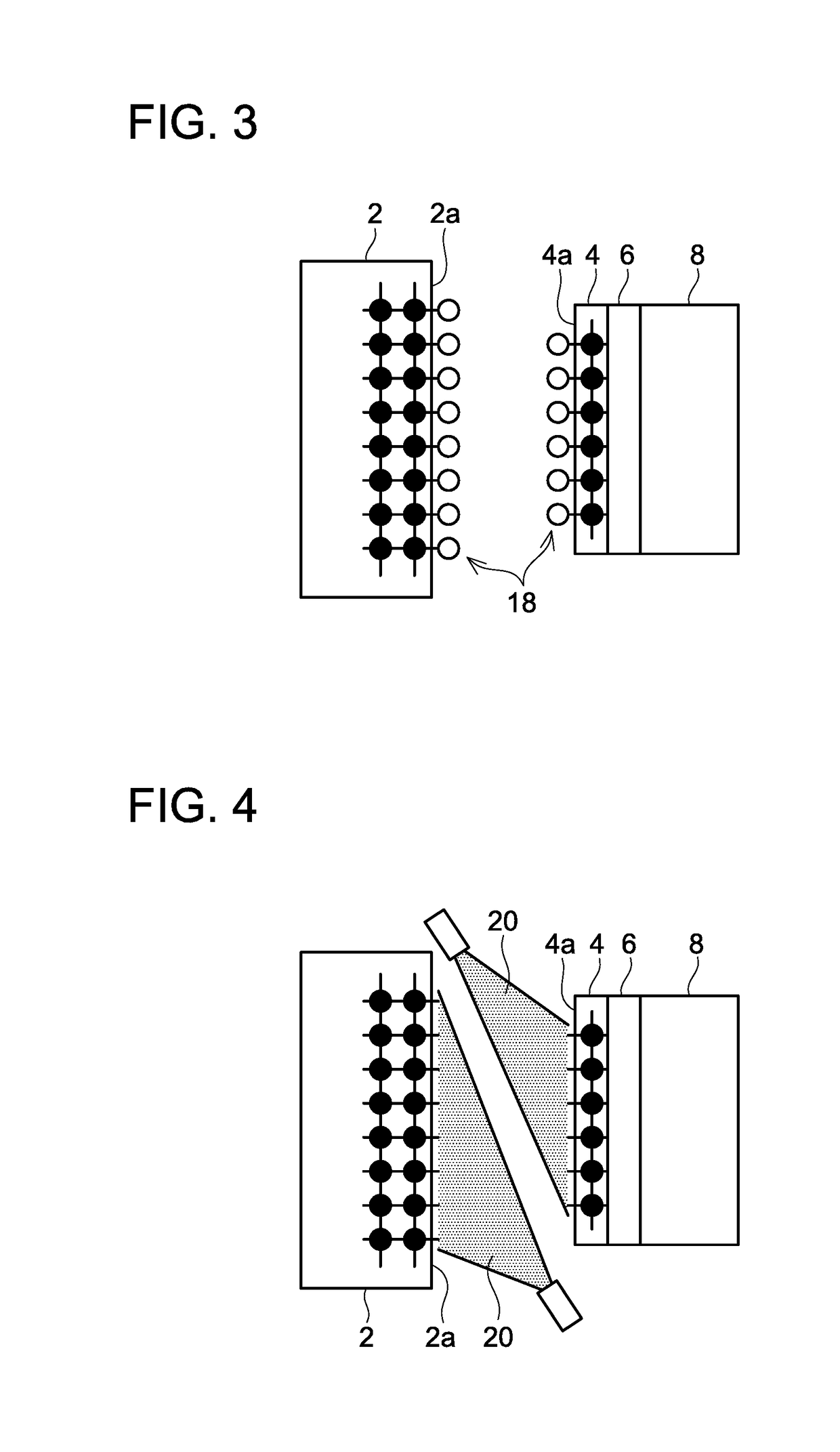
[0075]Reference signs 4 and 14 show heat sink like layers intervened between the heat sinks 2 and respective ones of the end coats 6, 12, and the presence of these same-material layers allows the heat sinks 2 and the laser media 8 to be joined by room temperature b...

third embodiment

Multi-Reflection Laser Apparatus

[0080]FIG. 8 shows a laser apparatus of a third embodiment, and excitation beam reflected in the laser medium 28 is reflected again to re-enter the laser medium 28. The laser medium 28 is thin (its distance along an average progressing direction of the excitation beam (x axis) is short), and as such, the excitation beam is not sufficiently absorbed by merely reciprocating within the laser medium 28 just once, thus the excitation beam is reflected in multi paths.

[0081]Reference sign 2 shows the heat sink, which is transparent to the excitation beam of 808 nm. Reference sign 4 shows the heat sink like layer, 6 shows the first end coat, 28 shows the laser medium (which is thinner than the laser medium 2 of the first and second embodiments), 30 shows the second end coat, and 32 shows an output coupler.

[0082]The first end coat 6 has a low reflectance to the excitation beam, and a high reflectance to the laser beam. The second end coat 30 has a high reflect...


PUM

PropertyMeasurementUnit
thicknessaaaaaaaaaa
diameteraaaaaaaaaa
thermal conductivityaaaaaaaaaa

Abstract

A technique which is suitable in joining an end surface of a laser medium to a transparent heat sink for maintaining thermal resistance therebetween low and avoiding large thermal stress from acting on the laser medium is to be provided. An end coat is provided on the end surface of the laser medium, a same-material layer constituted of a same material as the heat sink is provided on a surface of the end coat, a surface of the same-material layer and an end surface of the heat sink are activated in a substantially vacuum environment, and those activated surfaces are bonded in the substantially vacuum environment. A laser apparatus having low thermal resistance between the laser medium and the heat sink and high transparency at a joint interface therebetween, and no large thermal stress acting on the laser medium is thereby obtained.

Description

TECHNICAL FIELD[0001]The description herein discloses a laser apparatus (including laser oscillator and laser amplifier) utilizing solid-state laser medium (or gain medium) and a manufacturing method thereof.BACKGROUND ART[0002]A solid-state material which emits light when excitation beam enters therein is known. For example, a solid-state material with rare earth element dopants such as Nd:YAG, Yb:YAG, Nd:YVO4, Yb:YVO4, Nd:(s-)FAP, Yb:(s-)FAP emits light when the excitation beam enters therein. When such a solid-state material is installed in a laser oscillator, laser beam is discharged from the laser oscillator. The description herein refers to a solid-state material capable of receiving excitation beam and discharging laser beam from a laser oscillator as a laser medium. Further, a solid-state material that receives excitation beam and input beam to discharge output beam with amplified power of the input beam is also known. The description herein also refers to this type of solid...

Claims


Application Information

Patent Timeline
Patent Type & Authority Applications(United States)
IPC IPC(8): H01S3/04H01S3/042H01S3/16H01S3/11H01S3/08H01S3/06
CPCH01S3/0405H01S3/08059H01S3/1643H01S3/042H01S3/0604H01S3/2316H01S3/1611H01S3/094038H01S3/113H01S3/0627H01S3/0621H01S3/1115H01S3/07H01S3/08054H01S3/094084
Inventor TAIRA, TAKUNORIKAUSAS, ARVYDASZHENG, LIHEYAHIA, VINCENTYASUHARA, RYO
Owner INTER UNIV RES INST NAT INST OF NATURAL SCI
Why Eureka
Try Eureka