Ultrafast raman laser systems and methods of operation

a laser system and ultrafast technology, applied in the direction of laser details, basic electric elements, electrical equipment, etc., can solve the problems of poor coverage, cumbersome, complex and costly to be widely available, and the laser does not provide full spectral coverage, so as to shorten the optical length of the resonator cavity.

Inactive Publication Date: 2012-10-18
MACQUARIE UNIV
View PDF2 Cites 31 Cited by
  • Summary
  • Abstract
  • Description
  • Claims
  • Application Information

AI Technical Summary

Benefits of technology

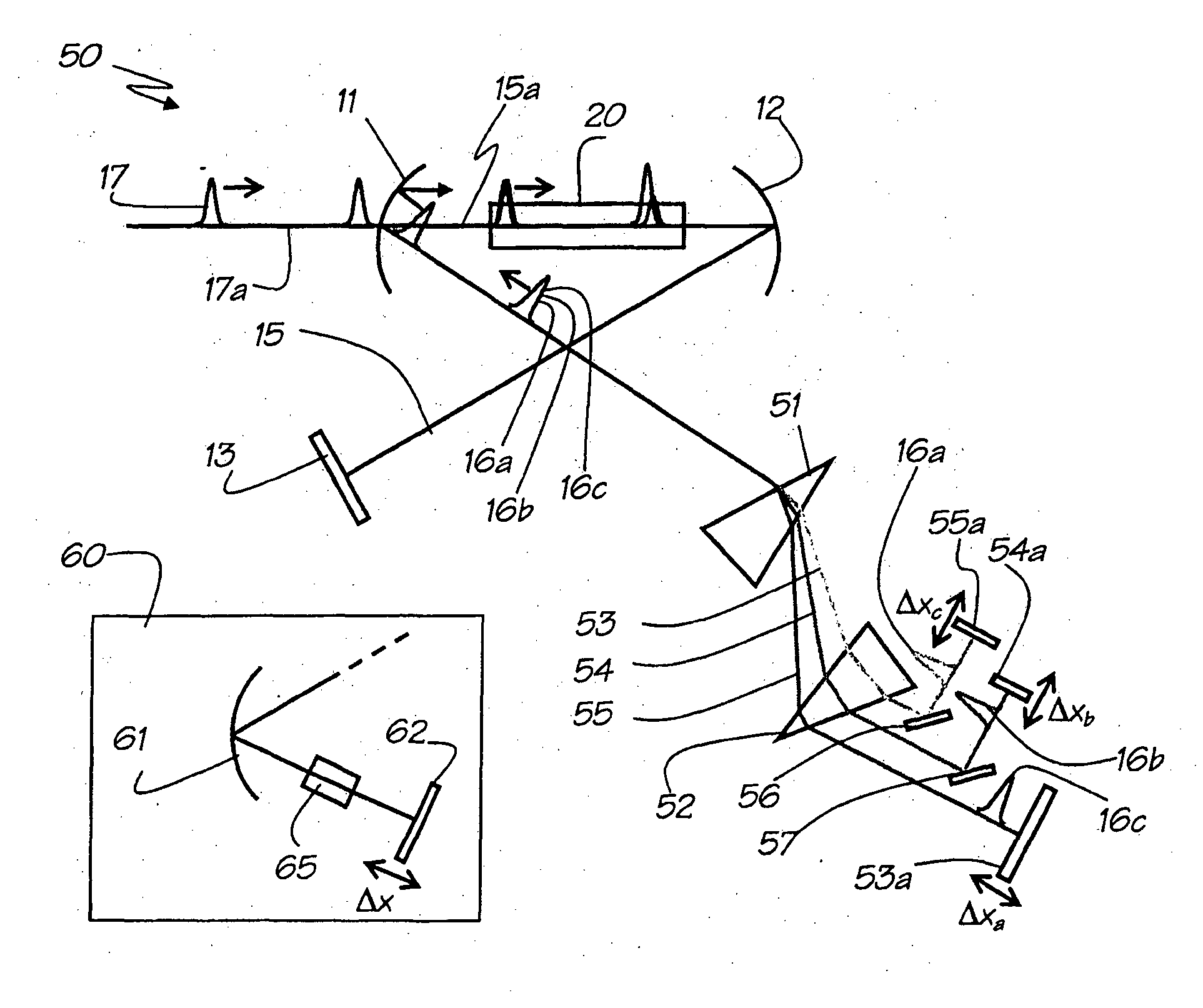
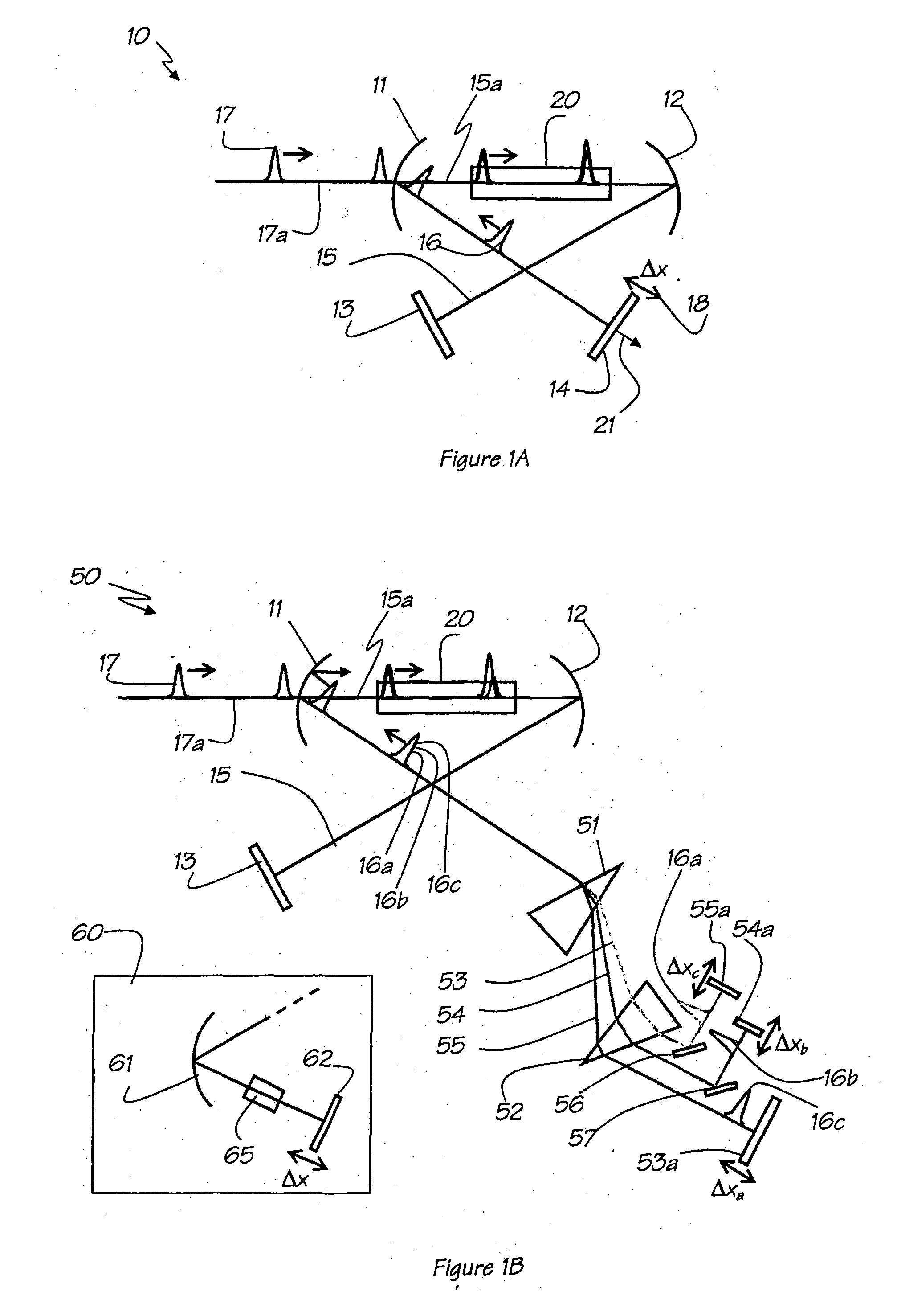
[0050]The adjustable reflectors may each comprise a translator attached thereto. Adjustment of the optical length of each of the coupled resonator cavities may comprise translating each of the respective adjustable reflectors along an optical axis of the respective coupled resonator cavity as seen by the respective spatially separated beam, thereby to either lengthen or shorten the optical length of the resonator cavity as seen by each spatially separated beam in accordance with requirements.

Problems solved by technology

These lasers do not provide full spectral coverage, and the yellow to red region between 550 nm and 700 nm is one key area where coverage is poor.
While the addition of other lasers and OPO technology in principle could provide full wavelength coverage, in practice this is too cumbersome, complex and costly to be widely available, and so researchers must face the limits imposed by the wavelength restrictions.
However, such systems are typically expensive and complex and require very close control of crystal temperature and angle.
Also, the crystals used in OPOs are often hygroscopic and degrade with time (grey-tracking).
Furthermore, wavelengths close to the pump wavelength are not accessible, and so a neodymium-pumped OPO must be pumped at 355 nm to generate in the yellow, at the cost of efficiency.
The development of a solid-state laser alternative to tunable visible dye laser technology has been the long-term goal of many laser physicists, and while OPOs have clear potential here, their uptake has been mostly restricted to physics laboratories, largely because of complexity issues.
However, the peak power requirements for three-photon absorption significantly exceed that for two-photon microscopy and hence this technique has limited applications in biological imaging.
Without a resonator, picosecond Stokes generation within one or two passes of the Raman medium can be efficient, the pulse power threshold is much higher than for resonant Raman lasers, the output spectrum is not easily controlled and the output beam is not of sufficient quality to meet the demands of most applications.
However, all of these schemes employed pulse energies of the order of μJ or even mJ, with the disadvantage of having lower duty cycle and require larger and more complex laser systems.
Also, successive pulses within the Q-switched train have different peak power, making them unsuitable for imaging and scanning applications such as scanning microscopy.

Method used


Image

  • Ultrafast raman laser systems and methods of operation
  • Ultrafast raman laser systems and methods of operation
  • Ultrafast raman laser systems and methods of operation

Examples


example 1

Ultrafast Synchronously Pumped Raman Laser System

[0137]In the present example, a single wavelength synchronously pumped Raman laser system 100 is disclosed schematically in FIG. 2, where HWP 107 is a Half Wave-Plate @532 nm; PBS is a polarizing beam splitter 108; and Δx represents the possible cavity detuning by translating output reflector M4104 along the axis of the resonator cavity 120. A mode-matching telescope system 118 was also employed to adjust the beam diameter of the pump beam 116 in Raman crystal 110 for mode-matching considerations i.e. to match the beam size of the pump beam in the crystal 110 with the size of the cavity mode at the position of the Raman crystal 110.

[0138]In the presently described example, the laser system 100 of FIG. 2 comprises a 50-mm-long KGW Raman crystal 110 as the stimulated Raman scattering (SRS) gain medium. The Raman crystal 110 was antireflection (AR) coated at 532 nm. The crystal 110 was oriented such that the pump beam 116 from a mode-loc...

example 2

Ultrafast Synchronously Pumped Diamond Raman Laser System

[0151]The present example describes an exemplary arrangement 200, depicted schematically in FIG. 5 of a mode locked Raman laser with diamond as the Raman medium, synchronously pumped by a mode locked laser in a further arrangement of a laser system similar to that of laser system 100 as disclosed in Example 1. Using diamond as the Raman crystal offers a greatly extended range of capability. The larger Stokes shift of diamond (1332 cm−1) compared to that of KGW (768 and 901 cm−1), enables an output wavelength of 573 nm from a single Stokes shift when using a 532 nm pump laser. Diamond also has a much higher gain coefficient enabling smaller crystals to be used. The longer dephasing time of diamond (6.8 ps) compared to 3.2 ps for KGW is expected to place a higher limit on the pulse duration and enable the testing of models for pulse compression limits in synchronously pumped Raman lasers as discussed below. Also, the outstanding...

example 3

Ultrafast Synchronously Pumped Multiwavelength Raman Laser System

[0166]In the present example, a further Raman laser system 300 is described, similar to that of the laser system 100 of Example 1, but configured for multi-wavelength and selectable wavelength output.

[0167]An arrangement of the multiwavelength laser system 300 is depicted schematically in FIG. 8 in which Raman crystal 310 (SRS gain medium) is a 50×5×5 mm potassium gadolinium tungstate (KGW) crystal. The Raman crystal 310 has an anti reflection coating at 532 nm, for normal incidence to minimise reflection losses off the crystal surface. The KGW Raman crystal 310 was pumped along its Nm axis to match the 901 cm−1 Raman shift with a pump beam 316 at 532 nm to provide a first Stokes wavelength of 559 nm and a second Stokes wavelength of 589 nm. The pump beam 316 was obtained from a pump source 315 which in the present arrangement was a CW mode-locked Nd:YAG laser producing 22 W at 1064 nm with a repetition rate of 78 MHz....


PUM


Abstract

A Raman laser system, the system comprising a resonator cavity comprising a plurality of reflectors, wherein at least one reflector is an output reflector adapted for outputting a pulsed output beam from the resonator cavity at a frequency corresponding to a Raman shifted frequency of the pump beam, wherein the output reflector is partially transmitting at the Raman-converted frequency; a solid state Raman-active medium located in the resonator cavity to be pumped by a pulsed pump beam having a pump repetition rate and for Raman-converting a pump pulse incident on the Raman-active medium to a resonating pulse at a Raman-converted frequency resonating in the resonator cavity; a resonator adjuster for adjusting the optical length of the resonator to match the round-trip time of the resonating Raman-converted pulse with the pump beam repetition rate such that the resonating pulse is coincident both temporally and spatially with a pump pulse in the Raman-active medium on each round trip, to Raman amplify the resonating pulse at the Raman-converted frequency in the Raman-active medium. Also a multiwavelength Raman laser system further comprising a dispersive element and a plurality of coupled resonator cavities. Also, methods for providing ultrafast pulsed Raman laser operation.

Description

TECHNICAL FIELD[0001]The present invention relates to ultrafast Raman laser systems and methods for their operation and in particular to mode-locked Raman laser systems and methods of operation and will be described hereinafter with reference to this application. However, it will be appreciated that the invention is not limited to this particular field of use.BACKGROUND[0002]Any discussion of the background art throughout the specification should in no way be considered as an admission that such background art is prior art, nor that such background art is widely known or forms part of the common general knowledge in the field.[0003]Ultrafast lasers are common in research laboratories, and the current main types are as follows: Neodymium based lasers (such as Nd:YVO4 and Nd:YAG) generate picosecond pulses at around 1064 nm, and can be frequency doubled or tripled to 532 nm and 355 nm; Ti:Sapphire lasers can have pulses as short as a few femtoseconds, and operate in the wavelength ran...

Claims


Application Information

Patent Timeline
Patent Type & Authority Applications(United States)
IPC IPC(8): H01S3/30
CPCH01S3/0057H01S3/0092H01S3/08086H01S3/0811H01S3/0816H01S3/30H01S3/105H01S3/109H01S3/1121H01S3/1675H01S3/094026
Inventor PASK, HELEN MARGARETSPENCE, DAVID JAMESGRANADOS, EDUARDOMILDREN, RICHARD PAUL
Owner MACQUARIE UNIV
Why Eureka
Try Eureka