Infrared vision sensing detection method and device for narrow-gap weld seam deviation

Active Publication Date: 2018-01-18
JIANGSU UNIV OF SCI & TECH
View PDF0 Cites 18 Cited by
  • Summary
  • Abstract
  • Description
  • Claims
  • Application Information

AI Technical Summary

Benefits of technology

The present invention provides an infrared vision sensing detection method and device for narrow-gap weld seam deviation. This method can be used with different types of arc such as shaking, swing, or rotating. It has high detection precision, strong environmental adaptability, and good practicability. Compared with existing methods, the present invention extracts weld seam deviation information based on the position of the welding wire relative to the left and right side walls of a groove, which avoids the impact of the asymmetric arc form on detection precision. The device can adjust in real time the positions of the welding wire image and the groove edge image capture windows according to changes in the arc and groove edge positions, improving its environmental adaptability. The relative position of the welding wire in the welding groove is detected according to two adjacent welding images, improving the real-time performance of the weld seam deviation detection. In cases where pulsed welding is performed using a shaking (or swing or rotating) arc, the detection method synchronized with the pulsed arc base value current used in the present invention can acquire a welding image with smallest interference from arc light, further improving the precision of the weld seam deviation detection.

Problems solved by technology

An actual narrow-gap gas metal arc welding (GMAW) process is often affected by factors such as a groove machining error, a workpiece assembly error, and a welding thermal deformation, causing changes in the groove gap size and the center position of the weld seam, and therefore, the center of a welding torch is deviated from the center of the weld seam (that is, weld seam deviation occurs).
In this case, even if a groove side wall penetration control technology based on the arc swing or rotation process is applied, the quality of narrow-gap welding is still affected.
The disadvantage of this method lies in that: the single-side groove edge position detection for weld seam deviation is only applicable to cases where the groove gap is constant, and is inapplicable to common situations where the groove gap is varying.
Therefore, the application range is small.
The disadvantages of the method lie in that: 1. During actual narrow-gap welding, the arc is generally asymmetric about the axis thereof, especially, when the arc is close to the edge on one side of the groove, the arc usually climbs along the side wall of the groove; therefore, when the geometric center of the arc is extracted according to the weld seam deviation identification method, it is difficult to accurately reflect the actual rotating center of the arc, thus affecting the precision of weld seam deviation detection, and also affecting the engineering practicability.
The arc center detection method for the weld seam deviation is only suitable for high-frequency rotating arc narrow-gap welding applications, and is not suitable for low-frequency swing (including shaking) arc narrow-gap welding application scenarios.
The used CCD camera has a small dynamic range and a low response speed, affecting the precision and real-time performance of the weld seam deviation detection.

Method used


Image

  • Infrared vision sensing detection method and device for narrow-gap weld seam deviation
  • Infrared vision sensing detection method and device for narrow-gap weld seam deviation
  • Infrared vision sensing detection method and device for narrow-gap weld seam deviation

Examples


embodiment 1 (

Using Shaking Arc Direct Current Welding as an Example)

[0066]FIG. 11 is an instance diagram of a welding wire axis position information extraction effect during direct current welding. The test conditions include: the digital CMOS infrared camera 11 works in an external triggering manner and has a camera angle of 25°, an aperture of 16, and an exposure time of 2 ms; the narrow bandpass filter has a central wavelength of 970 nm and a bandwidth of 25 nm; the transmittance of the neutral dimmer is 10%; welding is performed at a downhand position by using a direct current, the arc current is 280 A, the arc voltage is 29 V, the welding speed Vw=20.3 cm / min, the wire extension is 18 mm, the diameter of the welding wire is 1.2 mm, the flow rate of the welding shielding gas Ar+20%CO2 is 30 L / min, and the I-type low-carbon steel welding groove gap is 13 mm. At the time point corresponding to FIG. 11, the welding torch is deviated leftwards (or the weld seam is deviated rightwards) by 0.5 mm;...

embodiment 2 (

Using Shaking Arc Pulsed Welding as an Example)

[0071]FIG. 13 is an instance diagram of a welding wire axis position information extraction effect during pulsed welding. Test conditions include: the transmittance of the neutral dimmer is 30%, the digital infrared CMOS camera works in an external triggering manner, welding is performed using a pulsed MAG arc, an average welding current is 280 A, an average arc voltage is 29 V, and the welding torch is deviated rightwards (or the weld seam is deviated leftwards) 0.6 mm; other test conditions are the same as conditions in FIG. 11.

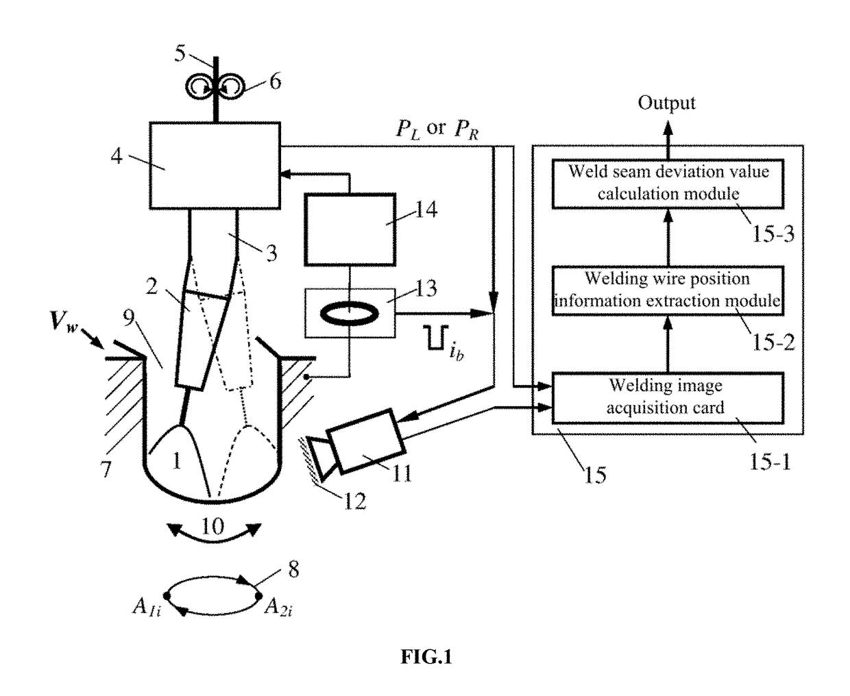
[0072]When the arc shakes to a position close to a side wall of the groove, a signal PL where the arc stops at the left side wall of the groove or a signal PR where the arc stops at the right side wall of the groove is valid. In this case, once the arc current sensor 13 detects that the first base value period current signal ib of the pulsed arc 1 arrives, the infrared camera 11 is triggered immediately to acqu...


PUM

PropertyMeasurementUnit
Interferenceaaaaaaaaaa
Distanceaaaaaaaaaa

Abstract

Disclosed are an infrared vision sensing detection method and device for narrow-gap weld seam deviation. The device includes a shaking (or rotating) arc narrow-gap welding torch, an arc current sensor (3), a computer image processing system (15), and an infrared photographing system. An infrared camera (11) acquires an infrared image of a welding region in an external triggering manner when an arc (1) shakes (or rotates) to a position closest to the left side wall or right side wall of a groove (9). After computer image processing, welding wire position and groove edge information is extracted in real time, and weld seam deviation is calculated according to position changes of a welding wire relative to the left side wall and the right side wall of the groove, and the weld seam deviation is output. During pulsed arc welding, a signal in a base value period of the arc current pulse is detected by using the current sensor, thereby realizing welding image acquisition synchronized with the base value current period of the pulsed arc. The device has a simple constitution, a wide application range, high weld seam detection precision, high environment adaptability, and high anti-interference capability.

Description

FIELD OF THE INVENTION[0001]The present invention relates to the field of welding technology, and in particular, to an infrared vision sensing method and device for detecting in real-time a shaking (or swing) or rotating arc narrow-gap weld seam deviation.DESCRIPTION OF RELATED ART[0002]An actual narrow-gap gas metal arc welding (GMAW) process is often affected by factors such as a groove machining error, a workpiece assembly error, and a welding thermal deformation, causing changes in the groove gap size and the center position of the weld seam, and therefore, the center of a welding torch is deviated from the center of the weld seam (that is, weld seam deviation occurs). If the weld seam is not tracked or controlled, the weld seam deviation may accumulate. In this case, even if a groove side wall penetration control technology based on the arc swing or rotation process is applied, the quality of narrow-gap welding is still affected. The sensing technology is the key to implementat...

Claims


Application Information

Patent Timeline
IPC IPC(8): B23K31/12G01B11/14G01B11/02G06T7/00G01R19/00
CPCB23K31/125G01B11/022G01B11/14G06T7/0004G06T7/13G06T7/73G06T7/136G06T7/155G01R19/0092G06T2207/10048G06T2207/30136G06T2207/20036G06T2207/20032B23K9/022B23K9/09B23K9/1274B23K9/173B23K9/0213B23K9/0216B23K9/0956G06T2207/30152
Inventor WANG, JIAYOUZHU, JIEZHANG, CAIYANG, MAOSENSU, NALI, WENHANG
Owner JIANGSU UNIV OF SCI & TECH
Why Eureka
Try Eureka