Wavelength tunable laser device and laser module

a laser device and laser module technology, applied in the direction of laser output parameters control, laser details, instruments, etc., can solve the problems of large variations in reflectance in the overlap portions, the fundamentally more difficult to achieve single-mode oscillation, and the mode spacing

Active Publication Date: 2018-01-25
FURUKAWA ELECTRIC CO LTD
View PDF8 Cites 23 Cited by
  • Summary
  • Abstract
  • Description
  • Claims
  • Application Information

AI Technical Summary

Benefits of technology

[0007]However, in DBR wavelength tunable laser devices of the type described above, elongating the cavity enough to obtain the narrow-linewidth laser light needed for coherent communications reduces the longitudinal mode spacing and makes it difficult to select just one cavity mode within the reflection bandwidth of the cavity, thereby making it fundamentally more difficult to achieve single-mode oscillation.

Problems solved by technology

However, in DBR wavelength tunable laser devices of the type described above, elongating the cavity enough to obtain the narrow-linewidth laser light needed for coherent communications reduces the longitudinal mode spacing and makes it difficult to select just one cavity mode within the reflection bandwidth of the cavity, thereby making it fundamentally more difficult to achieve single-mode oscillation.
Moreover, in a wavelength tunable laser device in which the cavity is configured using two ring resonators, any offset between the center wavelengths of the sharp reflection wavelength characteristics of the two results in large variations in reflectance in the overlapping portions.
Therefore, the peaks of the sharp reflection wavelength characteristics of the two ring resonators must be reliably aligned in order to achieve stable laser oscillation; however, achieving this degree of control is difficult.

Method used


Image

  • Wavelength tunable laser device and laser module
  • Wavelength tunable laser device and laser module
  • Wavelength tunable laser device and laser module

Examples


embodiment 1

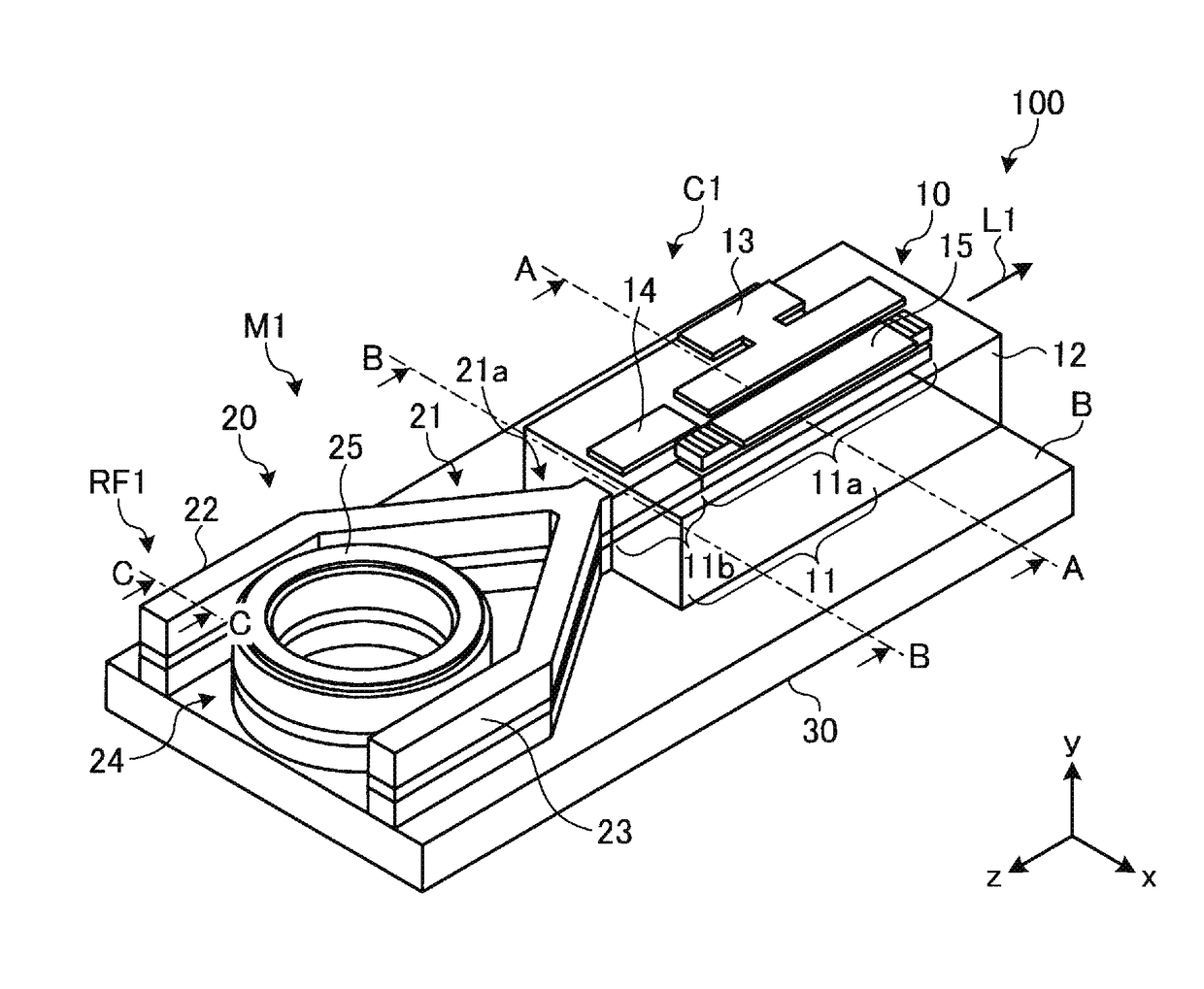
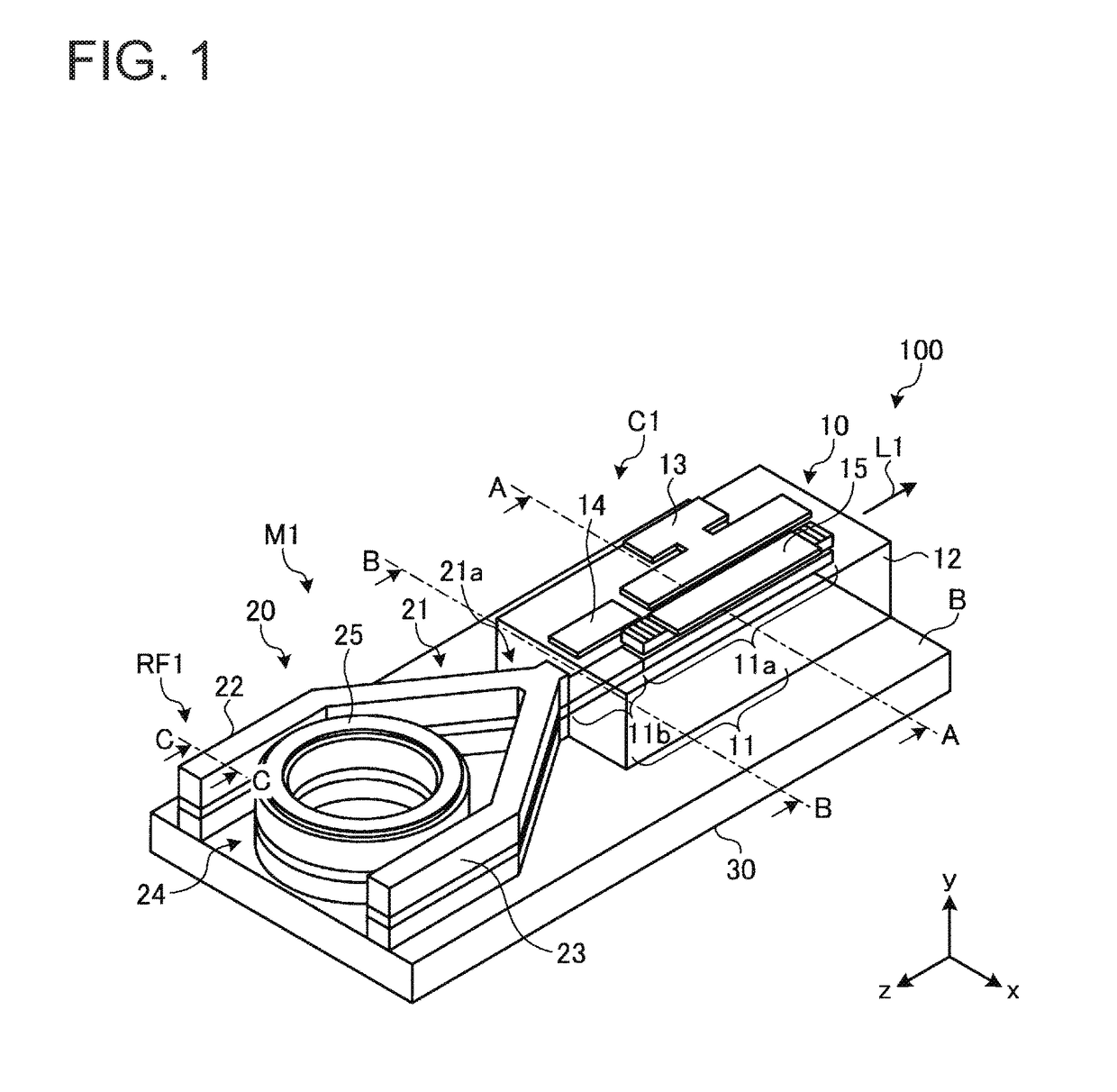
[0045]FIG. 1 is a perspective view schematically illustrating a wavelength tunable laser device according to Embodiment 1. A wavelength tunable laser device 100 is configured to achieve laser oscillation in the 1.55 μm band and output the resulting laser light. The wavelength tunable laser device 100 includes a first waveguide 10 and a second waveguide 20 formed on a common substrate B. The substrate B is made of n-type InP, for example. Moreover, an n-side electrode 30 is formed on the rear surface of the substrate B. The n-side electrode 30 is made of AuGeNi, for example, and is in ohmic contact with the substrate B.

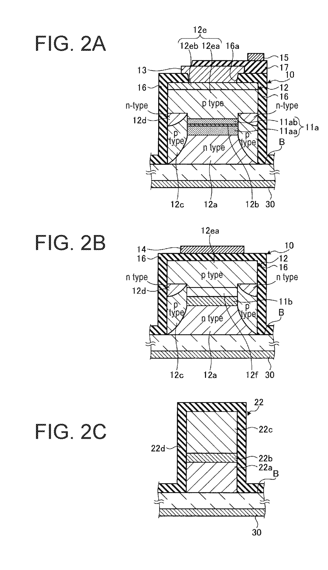
[0046]The first waveguide 10 includes a waveguide 11, a semiconductor stack 12, a p-side electrode 13, and microheaters 14 and 15 made of Ti. The waveguide 11 is formed extending in the Z direction within the semiconductor stack 12. A grating loaded gain portion 11a and a phase adjusting portion 11b are arranged within the first waveguide 10. The semiconductor stack 12...

embodiment 2

[0093]FIG. 11 is a perspective view schematically illustrating a wavelength tunable laser device according to Embodiment 2. As illustrated in FIG. 11, a wavelength tunable laser device 100A according to Embodiment 2 includes the wavelength tunable laser device 100 according to Embodiment 1 as illustrated in FIG. 1 as well as a semiconductor optical amplifier (SOA) 101 formed on a substrate B. The SOA 101 has a buried waveguide structure including an active core layer of the same material and structure as in the first waveguide. Here, however, no grating layer is included.

[0094]The wavelength tunable laser device 100 and the SOA 101 are optically coupled via a spatially coupled optical system (not illustrated in the figure). The laser light L1 output from the wavelength tunable laser device 100 is input to the SOA 101. The SOA 101 optically amplifies the laser light L1 and outputs the resulting light as laser light L2. The wavelength tunable laser device 100A according to Embodiment ...

embodiment 3

[0096]Next, Embodiment 3 will be described. Embodiment 3 is different from Embodiments 1 and 2 in that the second waveguide is a silicon (Si) photonic waveguide, for example.

[0097]FIGS. 12A and 12B schematically illustrate a wavelength tunable laser device according to Embodiment 3. FIG. 12A is a perspective view, and FIG. 12B is a cross-sectional view that will be described later. A wavelength tunable laser device 200 is configured to achieve laser oscillation in the 1.55 μm band and output the resulting laser light. The wavelength tunable laser device 200 includes a first waveguide 210 and a second waveguide 220.

[0098]The first waveguide 210 includes a waveguide 211, a semiconductor stack 212, an n-side electrode 213, and a microheater 215. The waveguide 211 is formed extending in the Z direction within the semiconductor stack 212. A gain portion 211a and a DBR grating layer 211b are arranged within the first waveguide 210. The semiconductor stack 212 is formed by stacking semicon...


PUM


Abstract

A wavelength tunable laser device includes: a laser cavity formed of a grating and a reflecting mirror including a ring resonator filter; a gain portion; and a phase adjusting portion. The grating creates a first comb-shaped reflection spectrum. The ring resonator filter includes a ring-shaped waveguide and two arms and creates a second comb-shaped reflection spectrum having peaks of a narrower full width than peaks in the first comb-shaped reflection spectrum at a wavelength interval different from that of the first comb-shaped reflection spectrum. One of the peaks in the first comb-shaped reflection spectrum and one of the peaks in the second comb-shaped reflection spectrum are overlapped on a wavelength axis, and a spacing between cavity modes is narrower than the full width at half maximum of the peaks in the first comb-shaped reflection spectrum.

Description

BACKGROUND OF THE INVENTIONTechnical Field[0001]The present invention relates to a wavelength tunable laser device and a laser module using the same.Background Art[0002]As coherent communication technologies have become more common, demand for narrow-linewidth wavelength tunable laser devices has increased. The configuration and principle of operation of wavelength tunable laser devices are described in detail in Non-Patent Document 1, for example. In general, reducing the linewidth of laser light output from a semiconductor laser device requires elongating the cavity. One known type of wavelength tunable laser device is the distributed Bragg reflector (DBR) variable wavelength laser, which utilizes a sampled grating to take advantage of the Vernier effect (see Patent Document 1, for example). In this type of wavelength tunable laser device, two DBRs in which portions of a diffraction grating are sampled are used in a semiconductor device. The reflection spectrums of these two DBR m...

Claims


Application Information

Patent Timeline
Patent Type & Authority Applications(United States)
IPC IPC(8): H01S5/14H01S5/00G02B5/28H01S5/06H01S5/026H01S5/0687
CPCH01S5/142H01S5/026H01S5/0687G02B5/284H01S5/0612H01S5/0085H01S5/06256H01S5/02415H01S5/0261H01S5/1014H01S5/1021H01S5/1032H01S5/1209H01S5/2275
Inventor KAWAKITA, YASUMASAHIGA, YASUTAKAIWAI, NORIHIROKUROBE, TATSURO
Owner FURUKAWA ELECTRIC CO LTD
Why Eureka
Try Eureka