
Rotary friction welding

Active Publication Date: 2018-02-01
ROLLS ROYCE PLC
View PDF2 Cites 5 Cited by
  • Summary
  • Abstract
  • Description
  • Claims
  • Application Information

AI Technical Summary

Benefits of technology

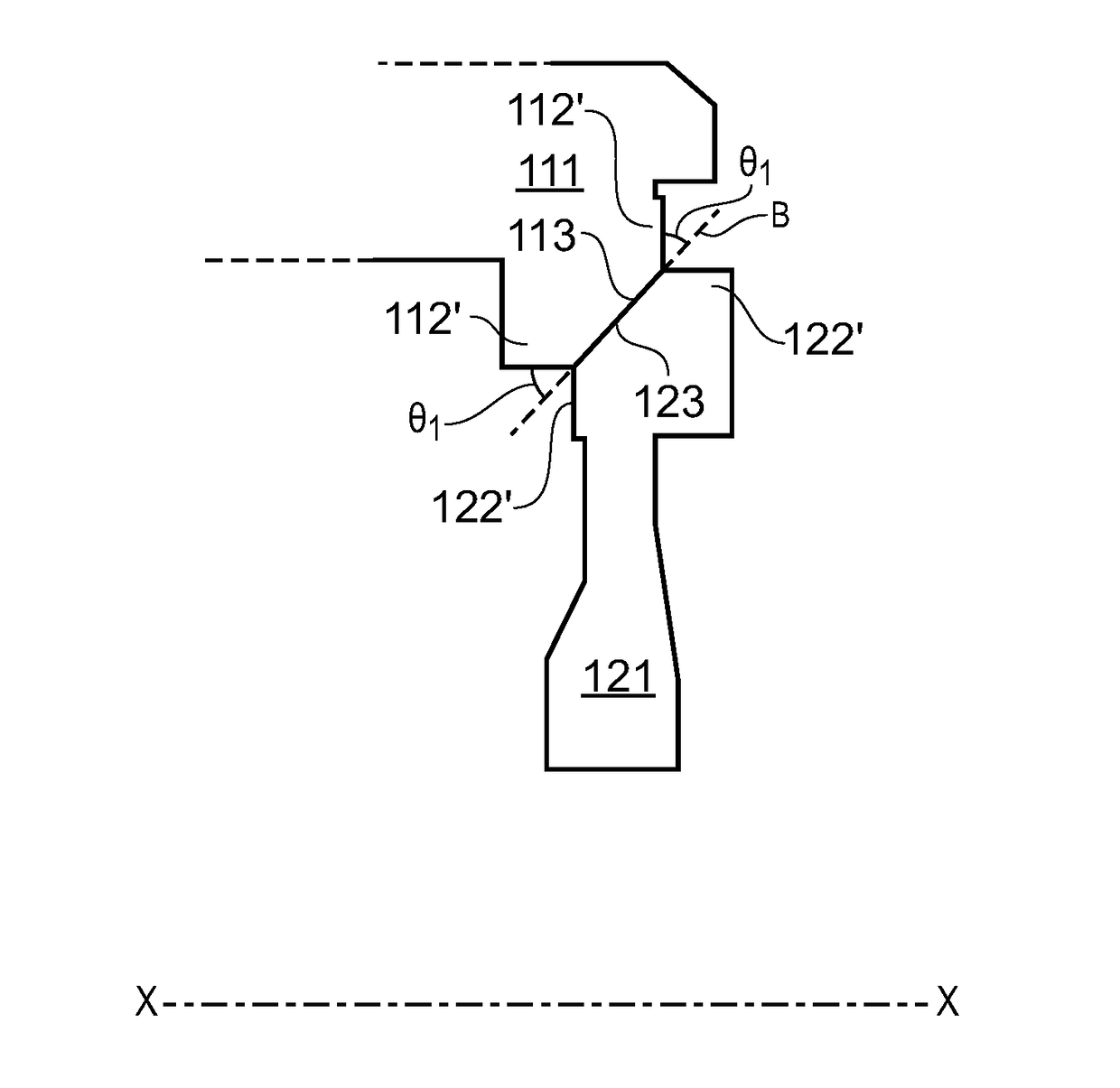
The patent describes a process for creating a multi-stage rotor assembly with weld interfaces at the inner side of the rim portion, which reduces temperatures and stresses. The weld surfaces are flanked by angled surfaces to control the flow of expelled material from the weld. The assembly has a reduced weight and increased service life compared to conventionally bladed assemblies. The technical effects include improved weld quality, reduced flow bias, and better sealing of the weld against contaminants.

Problems solved by technology

This is followed by upsetting when the temperature reaches a high enough level such that softening of the workpiece material allows the workpieces to be pushed together, with material being expelled sideways from a plasticised zone at the interface as flash.
The inertia weld can be life-limiting for such assemblies due to problems such as:Reduced mechanical performance and increased oxidation damage at high operating temperatures when the inertia weld forms a part of the wall of the working gas annulus,High residual stresses (hoop and axial) in the weld due to the high creep resistance of the alloy during post-weld heat treatment, which, in combination with high operating stresses, can over-stress the weld zone, and / orRecrystallised weld zones with microstructural attributes which promote increased fatigue crack growth rates and reduced low cycle fatigue life.
If the angle is too low, then the increased contact area during welding can exceed machine capacity and / or reduce the efficiency with which interface contaminants are expelled.
In contrast, if the angle is too high, a lack of sideways restraint under upsetting load can force the parts of the workpieces adjacent the weld interface radially inwardly or outwardly.

Method used


Image

  • Rotary friction welding
  • Rotary friction welding
  • Rotary friction welding

Examples


Embodiment Construction

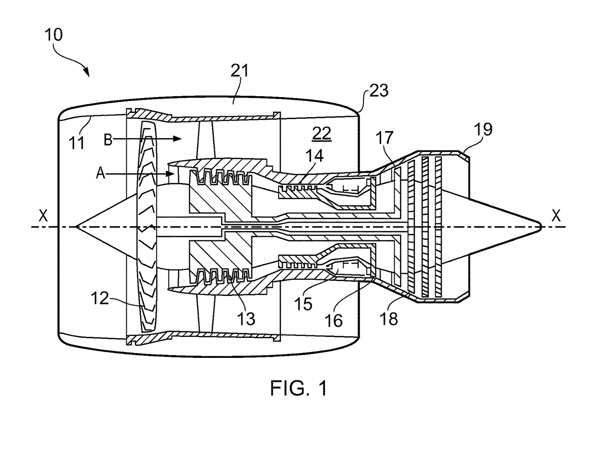
[0071]With reference to FIG. 1, a ducted fan gas turbine engine incorporating the disclosure is generally indicated at 10 and has a principal and rotational axis X-X. The engine comprises, in axial flow series, an air intake 11, a propulsive fan 12, an intermediate pressure compressor 13, a high-pressure compressor 14, combustion equipment 15, a high-pressure turbine 16, an intermediate pressure turbine 17, a low-pressure turbine 18 and a core engine exhaust nozzle 19. A nacelle 21 generally surrounds the engine 10 and defines the intake 11, a bypass duct 22 and a bypass exhaust nozzle 23.

[0072]During operation, air entering the intake 11 is accelerated by the fan 12 to produce two air flows: a first air flow A into the intermediate-pressure compressor 13 and a second air flow B which passes through the bypass duct 22 to provide propulsive thrust. The intermediate-pressure compressor 13 compresses the air flow A directed into it before delivering that air to the high-pressure compre...


PUM

PropertyMeasurementUnit
Angleaaaaaaaaaa
Angleaaaaaaaaaa
Angleaaaaaaaaaa

Abstract

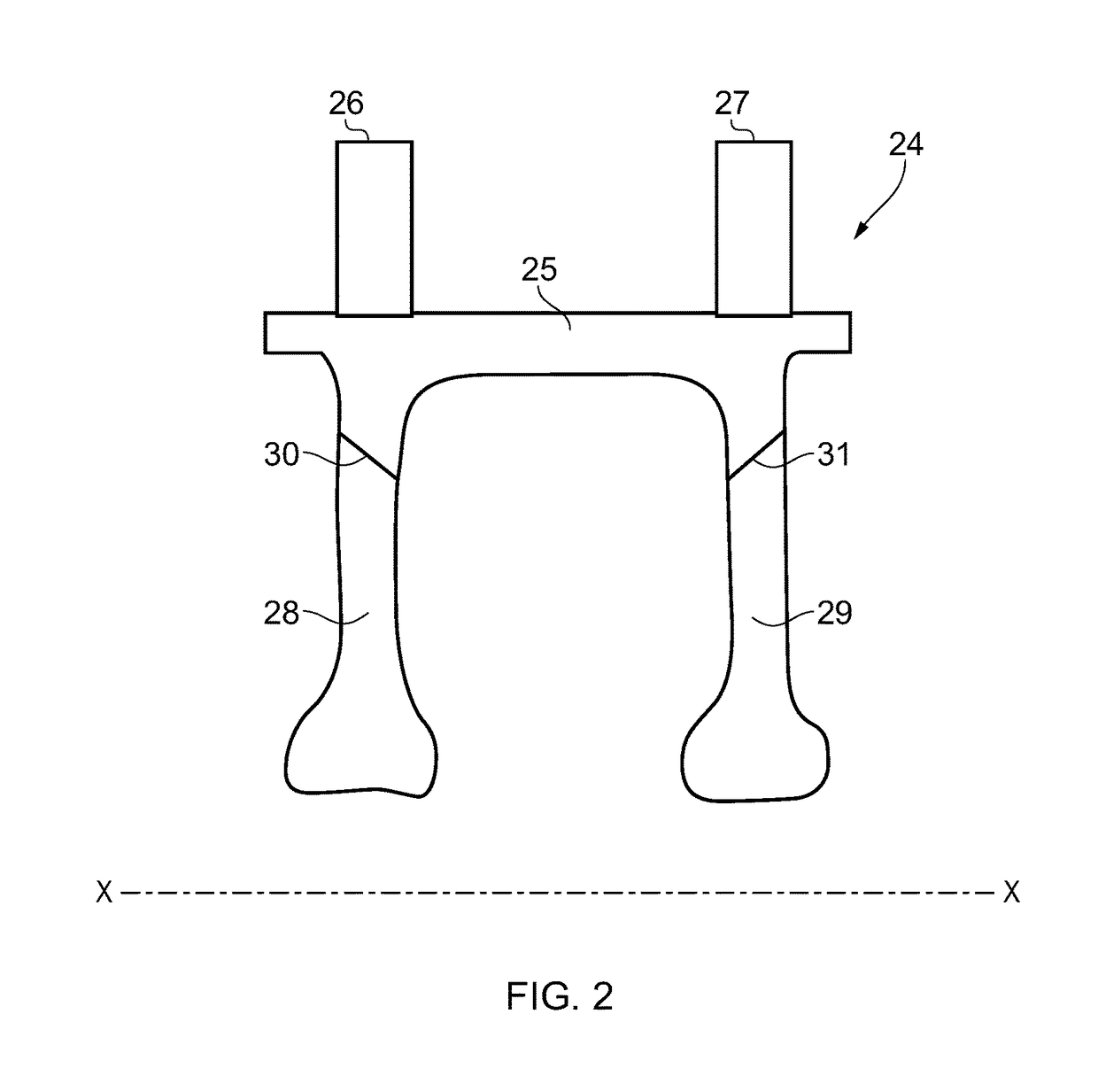
The present disclosure provides a rotary friction welding process including: providing an outer axisymmetric workpiece having a front first annular weld surface at a radially inward extent and a rear first annular weld surface at a radially inward extent; providing a front inner axisymmetric workpiece, the front inner workpiece having a front second annular weld surface at a radially outward extent of the front inner workpiece; providing a rear inner axisymmetric workpiece, the rear inner workpiece having a rear second annular weld surface at a radially outward extent of the rear inner workpiece; and rotary welding the workpieces together.

Description

CROSS-REFERENCE TO RELATED APPLICATIONS[0001]This specification is based upon and claims the benefit of priority from UK Patent Application Number 1612911.6 filed on 26 Jul. 2016, the entire contents of which are incorporated herein by reference.BACKGROUND1. Field of the Disclosure[0002]The present disclosure relates to a rotary friction welding process.2. Description of the Related Art[0003]Rotary friction welding is a process for welding together two bodies or workpieces by converting mechanical energy to heat energy by the friction between the engaging weld surfaces of the two workpieces. The process involves effecting relative rotation between the two workpieces while the weld surfaces remain in engagement with each other.[0004]For example, in inertia friction welding one of two coaxial workpieces is attached to a flywheel, rotated to a predetermined speed and then driven against the second workpiece using thrust supplied by the welding machine. A fixed amount of stored energy i...

Claims


Application Information

Patent Timeline
IPC IPC(8): B23K20/12F01D5/06B23K20/22B23P15/00B23P15/04
CPCB23K20/129B23P15/006B23P15/04B23K20/22F05D2230/10B23K2201/001B23K2203/18F05D2220/32F05D2230/239F01D5/063B23K20/12B23K33/006B23K2101/001B23K2103/18F04D29/023F04D29/321F05D2230/53F05D2300/6032F01D5/06
Inventor BRAY, SIMON E.WALPOLE, ANDREW R.
Owner ROLLS ROYCE PLC
Learn More