Skull implanted magnet assembly for brain stimulation

a magnet assembly and skull technology, applied in the field of skull implanted magnet assembly for brain stimulation, can solve the problems of inability to predict the effect of the patient's brain activity, and inability to fully absorb the magnetic field, so as to achieve the effect of increasing the cognitive performance of the patien

Active Publication Date: 2018-03-01
NAT GUARD HEALTH AFFAIRS +2
View PDF1 Cites 8 Cited by
  • Summary
  • Abstract
  • Description
  • Claims
  • Application Information

AI Technical Summary

Benefits of technology

[0031]In one embodiment of the method, the cognitive performance of the patient is increased relative to a second patient not receiving a magnetic field from a magnet or an electromagnet.

Problems solved by technology

Sometimes a person may have discomfort at the site on the head where the magnet is placed.
Mild headache or brief lightheadedness may result.
It is also possible that the procedure could cause a seizure, although documented incidences of this are uncommon.
Because the treatment is new, however, long-term side effects are unknown.
Not all scientists agree on the best way to position the magnet on the patient's head or give the electromagnetic pulses.
They also do not yet know if rTMS works best when given as a single treatment or combined with medication.
Clinical trials studying the effectiveness of rTMS reveal mixed results.
However, its effect on treatment-resistant depression is not yet established.

Method used


Image

  • Skull implanted magnet assembly for brain stimulation
  • Skull implanted magnet assembly for brain stimulation
  • Skull implanted magnet assembly for brain stimulation

Examples


example 1

Constructing a Magnet-Loaded Skull Screw

[0106]A magnetic skull screw may be machined from titanium by the following procedure, which is summarized in FIG. 3:[0107]1. Start with a titanium rod material cut to an appropriate length as a screw blank.[0108]2. Remove a cap section from the blank.[0109]3. Drill an axial hole at the tip end of the screw blank where the magnet will be inserted.[0110]4. Insert and secure the magnet in the axial hole.[0111]5. Weld the cap into the body of the screw under inert gas and special cooling. Perform a leak test using a helium mass spectrometer.[0112]6. Machine the screw to its final shape. Perform a leak test using a helium mass spectrometer.[0113]7. Finish the surface by anodizing, texturing, or ion implant.

example 2

Shape of the Magnetic Field

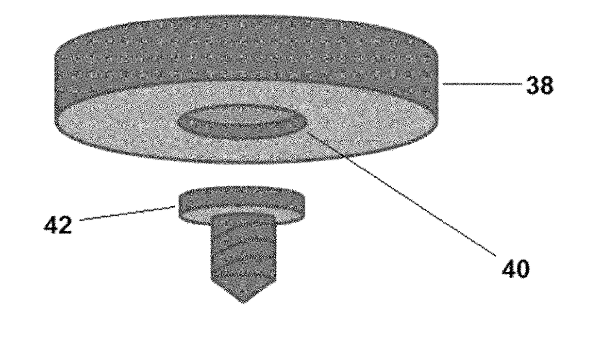
[0114]One half of a simulated absolute magnetic field strength from two magnets is shown in FIG. 9. The arrangement and shape of the magnets, which are outlined by the dotted lines, approximates those in the implantable magnet assembly: the top magnet is a disc-shaped magnet, and the bottom magnet is a cylindrical rod-shaped magnet, with the left side of the plot being the rotational axis of symmetry for both magnets. Magnetic field lines are also shown. To reduce artifacts, the simulation assumes the magnets to be in free space, rather than housed within an assembly. The lowest magnetic field strength represented is about 100 times stronger than the Earth's magnetic field.

example 3

Strength of the Magnetic Field from the Magnet-Loaded Skull Screw

[0115]The magnetic field near the tip of the skull screw is solenoidal in geometry and depends on a number of parameters. The axial field strength was calculated for the following parameters and assumptions:[0116]a) Screw length: 40 mm[0117]b) Screw diameter: 7 mm[0118]c) Magnet material: NdFeB, Brmax (residual flux density)=1.2 T[0119]d) Magnet dimensions: 8 mm long, 1.5 mm diameter[0120]e) Magnet to tip spacing: 5 mm

[0121]These parameters produce a magnetic strength along the axis from the tip of the screw as shown in FIG. 10. It is useful to compare these values with the magnetic field of the Earth. The magnetic field strength at the surface of the Earth varies considerably but averages about 0.04 mT. As FIG. 10 shows, the magnetic field 1 cm from the tip of the magnet-loaded skull screw is about 150 times larger than that of the Earth.

[0122]The magnetic field strength near either end of the magnet, but off axis, is...


PUM


Abstract

A skull-implantable magnet assembly for delivering a static magnetic field to a patient's brain, comprising a rod-shaped magnet housed within a skull screw, removably attached to a casing housing at least one flat magnet, is described. Details of the exterior construction are discussed, as well as magnet arrangements and methods of treating a brain tumor or neurological ailment of a patient.

Description

BACKGROUND OF THE INVENTIONTechnical Field[0001]The present invention relates to a magnet assembly comprising a magnetic screw configured to traverse a patient's skull to stimulate the patient's brain with a static magnetic field, and methods of use.Description of the Related Art[0002]The “background” description provided herein is for the purpose of generally presenting the context of the disclosure. Work of the presently named inventors, to the extent it is described in this background section, as well as aspects of the description which may not otherwise qualify as prior art at the time of filing, are neither expressly or impliedly admitted as prior art against the present invention.[0003]Transcranial magnetic stimulation has been suggested as a possible therapeutic tool in treating superficial cortical tumors and relieving vascular spasm and depression. In behavioral models of depression, magnetic stimulation has induced similar effects to those of electroconvulsive shock. There...

Claims


Application Information

Patent Timeline
Patent Type & Authority Applications(United States)
IPC IPC(8): A61N2/06A61N2/00
CPCA61N2/008A61N2/06
Inventor ALAM, IMRAN KHURSHID
Owner NAT GUARD HEALTH AFFAIRS
Why Eureka
Try Eureka