Inrush current limiter circuit

Active Publication Date: 2018-03-22
EXPRESS IMAGING SYST
View PDF5 Cites 13 Cited by
  • Summary
  • Abstract
  • Description
  • Claims
  • Application Information

AI Technical Summary

Benefits of technology

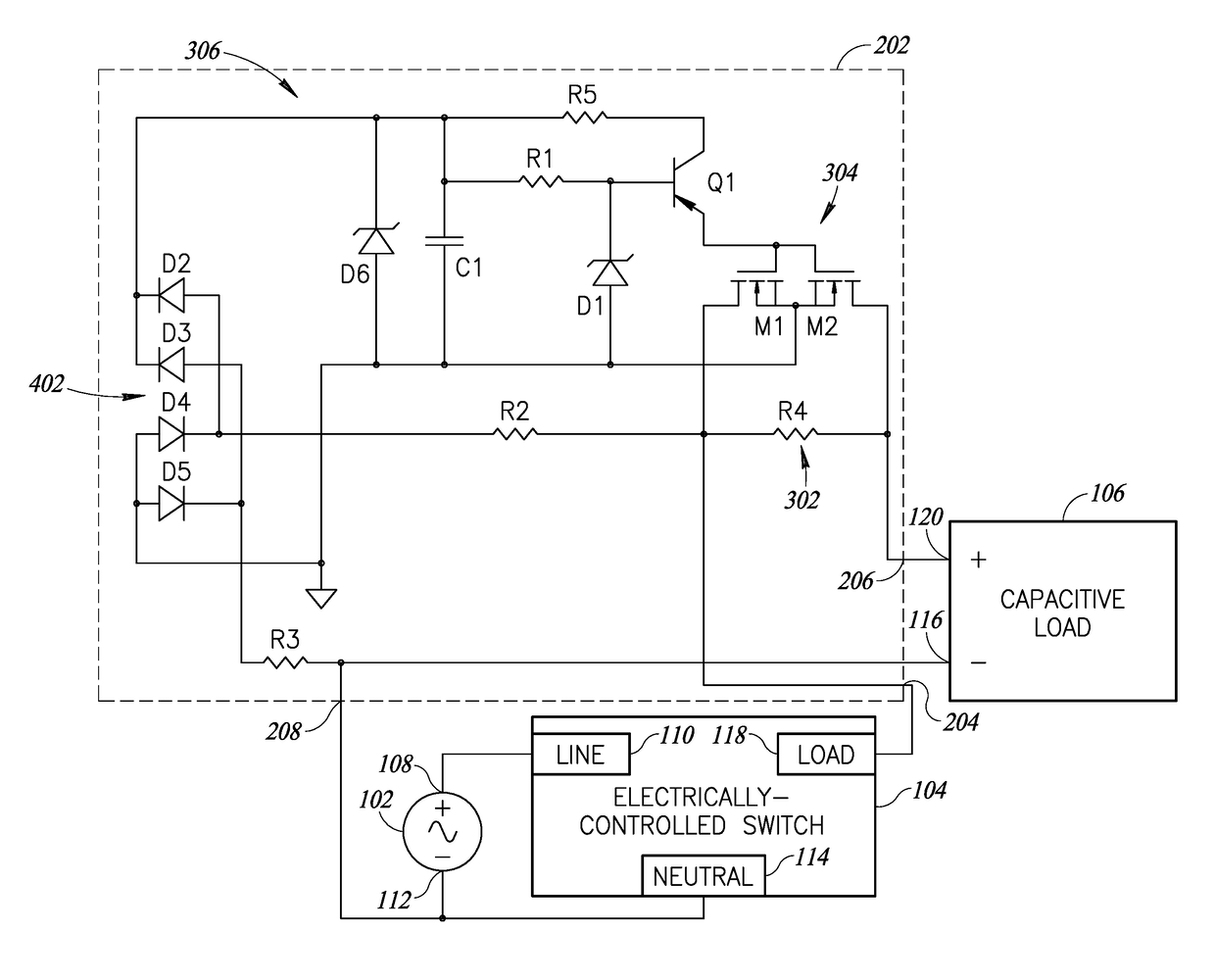
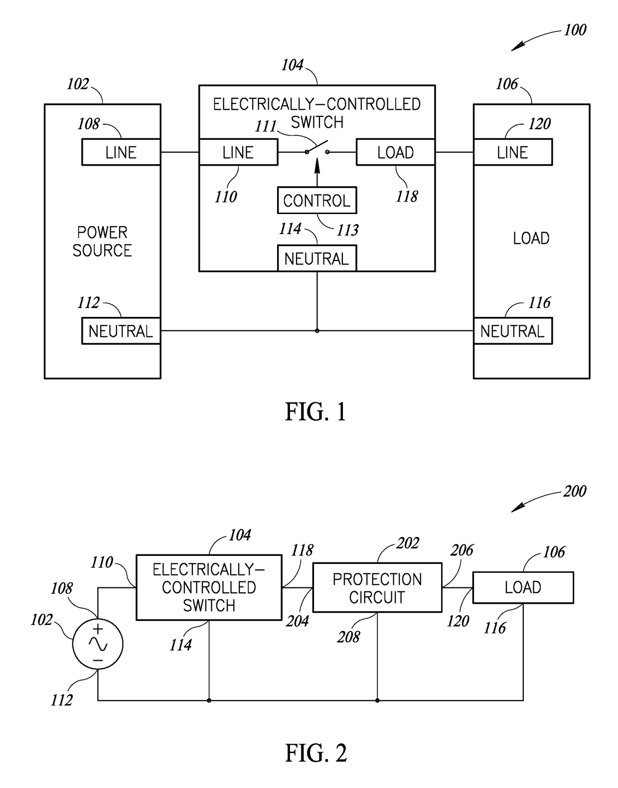
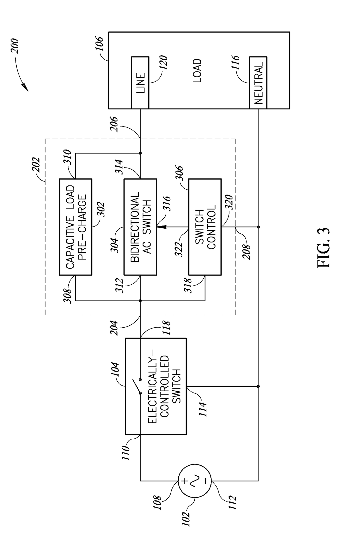
[0009]An inrush current protection circuit may be summarized as including an input terminal electrically coupleable to an output terminal of a control switch, the control switch selectively couples an alternating current (AC) power source to a load; an output terminal electrically coupleable to the load; a load pre-charge circuit electrically coupled between the input terminal and the output terminal; a bidirectional AC switch including a switch input terminal, a switch output terminal, and a switch control terminal, the switch input terminal electrically coupled to the input terminal of the protection circuit and the switch output terminal electrically coupled to the output terminal of the protection circuit such that the bidirectional AC switch is electrically coupled in parallel with the load pre-charge circuit, the bidirectional AC switch having an opened state, in which the bidirectional AC switch has a high resistance which inhibits AC flow, and a closed state, in which the bidirectional AC switch has a low resistance which permits AC flow; and a switch control circuit electrically coupled to the switch control terminal of the bidirectional AC switch and electrically coupleable to the input terminal of the protection circuit to

Problems solved by technology

Conventional photocontrols used with luminaires suffer from a number of drawbacks.
For example, a typical electro-mechanical relay used with a photocontrol for a luminaire may have a relatively short life span.
Arching caused by high capacitive in-rush currents of electronically ballasted luminaires and inductive “kick back” of magnetically ballasted luminaires can corrode the contactors of the electro-mechanical relays.
Circuitry that regulates electrical power supplied to such solid-state light source (e.g., LED drivers) may draw relatively high inrush currents when the light sources are switched on.
The inrush currents of electrically ballasted light sources may cause more damage to the contactors of electro-mechanical relays than is caused by the kickback currents of magnetically ballasted light sources.
Accordingly, when conventional photocontrols having electro-mechanical relays are used with luminaires having solid-state light sources, the electro-mechanical r

Method used


Image

  • Inrush current limiter circuit
  • Inrush current limiter circuit
  • Inrush current limiter circuit

Examples


Embodiment Construction

[0018]In the following description, certain specific details are set forth in order to provide a thorough understanding of various disclosed implementations. However, one skilled in the relevant art will recognize that implementations may be practiced without one or more of these specific details, or with other methods, components, materials, etc. In other instances, well-known structures associated with computer systems, server computers, and / or communications networks have not been shown or described in detail to avoid unnecessarily obscuring descriptions of the implementations.

[0019]Unless the context requires otherwise, throughout the specification and claims that follow, the word “comprising” is synonymous with “including,” and is inclusive or open-ended (i.e., does not exclude additional, unrecited elements or method acts).

[0020]Reference throughout this specification to “one implementation” or “an implementation” means that a particular feature, structure or characteristic de...


PUM


Abstract

Systems and methods for reducing inrush current into a component, such as a power converter (e.g., LED driver), which receives alternating current (AC) power from an AC power source (e.g., AC mains). The method may include pre-charging the input capacitance of a component or circuit for a determined period of time after closing of a control switch (e.g., photocontrol, contactor) using a capacitive load pre-charge circuit (e.g., resistor), and then shorting the capacitive load pre-charge circuit using a bidirectional AC switch coupled in parallel with the capacitive load pre-charge circuit after the determined period of time to selectively bypass the capacitive load pre-charge circuit. The bidirectional AC switch may include two source-connected metal oxide semiconductor field-effect transistors (MOSFETs) which have a very low “on resistance,” such that during steady-state operation, the protection circuit wastes very little power compared to conventional inrush protection circuits.

Description

BACKGROUNDTechnical Field[0001]The present disclosure generally relates to protection of components from damage caused by excessive electrical current.Description of the Related Art[0002]A photocontrol is a device that switches or controls electrical loads based on ambient light levels. As an example, a photocontrol can be used as a switch that provides electrical power to a luminaire only when detected light levels are below a desired level. Photocontrols used for such luminaires may include photosensors that are electrically and operably coupled to switching devices rated for use at relatively high line voltages (e.g., 90 VAC to 600 VAC) and at relatively high currents (e.g., amperes and higher). For example, a photocontrol for a luminaire may include a photosensor that controls an electro-mechanical relay coupled between a source of electrical power and a control device (e.g., a magnetic or electronic transformer) within the luminaire. The electro-mechanical relay may be configur...

Claims


Application Information

Patent Timeline
IPC IPC(8): H02H9/00H05B33/08H02H1/04H05B44/00
CPCH02H9/001H05B33/0887H02H1/043H02M1/32H02M1/36H05B45/50Y02B20/30H05B47/25
Inventor REED, WILLIAM G.
Owner EXPRESS IMAGING SYST
Why Eureka
Try Eureka