Stray-light tolerant lidar measurement system and stray-light tolerant lidar measurement method

a technology of straylight and lidar, which is applied in the direction of measurement devices, instruments, climate sustainability, etc., can solve the problems of unavoidable interference in the measurement system, inadequate numerical suppression procedure, and insufficient function, etc., and achieves simple design, easy to carry out, and determined quickly. flexible

Active Publication Date: 2018-04-12
BRINKMEYER ERNST
View PDF0 Cites 26 Cited by
  • Summary
  • Abstract
  • Description
  • Claims
  • Application Information

AI Technical Summary

Benefits of technology

[0015]The same as in WO 2014/072514 A1, the object of the present invention is likewise to provide a lidar measurement system having a simple design and a lidar measurement method that is easily carried out, with which the presence and/or the movement of particles or objects in an extended remote spatial region may be determined quickly, flexibly, and with a selectable spatial resolution. In contrast to W

Problems solved by technology

However, the procedure described therein for numerical suppression of interference is not adequate, since for multiple interferences, each suppression described leaves behind residual signals when other interferences are intentionally suppressed.
In addition, the described suppression method is focused only on discrete interference points, and does not function satisfactorily when the interference signals, arising in distributed form due to Rayleigh scattering in the fiber segment between the circulator and the transmitting-receiving lens/telescope, are to be suppressed.
Efficient suppression

Method used


Image

  • Stray-light tolerant lidar measurement system and stray-light tolerant lidar measurement method
  • Stray-light tolerant lidar measurement system and stray-light tolerant lidar measurement method

Examples


Embodiment Construction

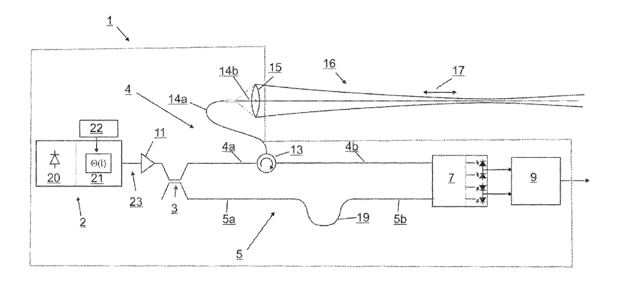
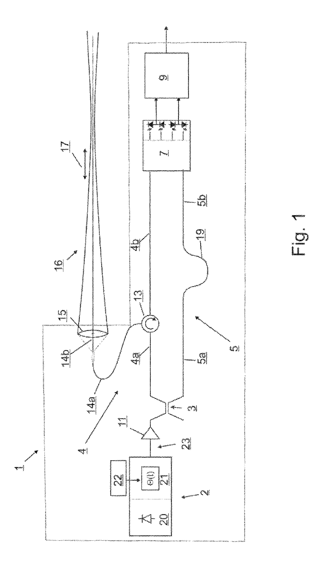
[0061]The lidar measurement system schematically shown in FIG. 1 has a continuous-wave laser source (2) with an output power of 1 mW, for example, and a wavelength of 1530 nm, for example; the light of the lidar measurement system passes through an erbium fiber amplifier (11) having an output power of 1 W, for example, and is then split by a beam splitter (3) in the form of an asymmetrical fiber-optic coupler into a partially fiber-optically defined measuring branch (4) and a completely fiber-optically defined reference branch (5). The splitting by the coupler (3) takes place, for example, at a 1000:1 ratio; i.e., for example 0.1 percent of the output light intensity of the amplifier (11) is coupled into the reference branch. Alternatively, the fiber amplifier (11) may also be situated in the measuring branch (4), in which case the splitting ratio of the coupler (3) may be 1:1, for example. The optical fibers used are preferably monomode fibers with low attenuation and a field radiu...


PUM


Abstract

A stray-light tolerant LIDAR measurement system. The system comprises an interferometer assembly having a continuous-wave laser source, a photodetection arrangement and optical components. The laser source comprises a laser-light-generating component, a downstream optical phase modulator and a control unit connected to the modulator to deliver a control signal corresponding to a pseudo-noise signal defined by a predetermined phase function. The interferometer assembly comprises an evaluation unit which is coupled to the interferometric photodetector assembly to detect the detector signals of same and to determine the presence and/or movement of particles and/or objects from the detector signals wherein, in the case of two wavelengths emitted from the laser light generating components, the detector signals are detected separately in two wavelength regions, and the phase function has a predetermined step-like time course and the evaluation unit scans the detector signals in synchrony with the timing of the steps of the phase function.

Description

RELATED APPLICATIONS[0001]The present application is a National Phase entry of PCT Application No. PCT / DE2016 / 100110, filed Mar. 11, 2016, which claims priority to German Patent Application No. 10 2015 004 272.6, filed Apr. 7, 2015, the disclosures of which are hereby incorporated by reference herein in their entirety.FIELD OF THE INVENTION[0002]The present invention relates to a stray light-tolerant lidar measurement system for detecting the presence and / or movement of particles and / or objects in a spatial region that is remote from the lidar measurement system, and a method for detecting the presence and / or movement of particles and / or objects in a remote spatial region, using such a lidar measurement system.BACKGROUND OF THE INVENTION[0003]Lidar (light detection and ranging) is a method that is closely related to radar, and utilizes laser light instead of the radio waves used in the case of radar. Lidar may be used to make a remote measurement of various atmospheric parameters, a...

Claims


Application Information

Patent Timeline
IPC IPC(8): G01S17/58G01S17/95G01S7/491G01S7/481G01S17/32
CPCG01S17/58G01S17/95G01S7/4917G01S7/4818G01S17/32G01S7/493Y02A90/10
Inventor BRINKMEYER, ERNST
Owner BRINKMEYER ERNST
Why Eureka
Try Eureka