Method for providing a magnetic sensor with a biasing spin-orbit effective field

Inactive Publication Date: 2018-04-19
NAT UNIV OF SINGAPORE
View PDF2 Cites 15 Cited by
  • Summary
  • Abstract
  • Description
  • Claims
  • Application Information

AI Technical Summary

Benefits of technology

[0018]According to a first aspect there is provided a magnetic sensor which uses the so-called spin-orbit torque (SOT) effect. The magnetic sensor comprises a sensor element with an easy axis and a hard axis which is able to generate a spin-orbit torqu

Problems solved by technology

A primary drawback of barber pole bias is that only a small portion of the sensing element is active.
Moreover, the process for forming such kind of structure is complex, thereby increasing the overall cost of the sensor.
One significant drawback of this scheme is that the bias field usually is not uniform across the longitudinal direction of the sensor.
If the center portion is properly biased, then it is unavoidable that the edge regions will be over-biased, leading to the formation of so-called dead regions.
These inactive regions will generally degrade the sensitivity of the sensor.
However, comparative studies of magnetic noise in sensors with a contiguous junction and lead overlaid design showed that magnetic noise is twice as large as Johnson noise for a lead overlaid design, while it is comparable with Johnson noise for the contiguous junction design.
Although the uniformity of bias can be improved by other bias techniques such

Method used


Image

  • Method for providing a magnetic sensor with a biasing spin-orbit effective field
  • Method for providing a magnetic sensor with a biasing spin-orbit effective field
  • Method for providing a magnetic sensor with a biasing spin-orbit effective field

Examples


example 1

r

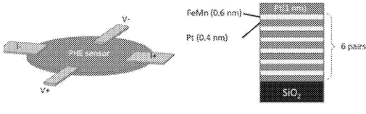
[0080]FIG. 1(b) explains the working principle of SOT-biased PHE sensor compared to a convention PHE design without biasing capability. In this specific example, the sensing element is a FM / HM bilayer. Current flows in the sensor between the two electrodes (marked I+ and I−), and the PHE signal is detected across the two voltage probes (marked V+ and V−). The current plays a two-fold purpose, i.e., serving as a sense current and at the same time generating a SOT bias field (Hbias). The bias field is perpendicular to the current direction. The role of the bias field is also two-fold in the PHE sensor of the current invention. On one hand, it cancels the effect of any undesirable field such as the earth field and makes the sensor's linear range symmetrical with respect to the external field and on the other hand, it helps to stabilize the domain structure. The actual sensor has an elliptic shape. The elongated shape serves to induce moderate shape anisotropy in the current direction....

example 2

ation Mechanism

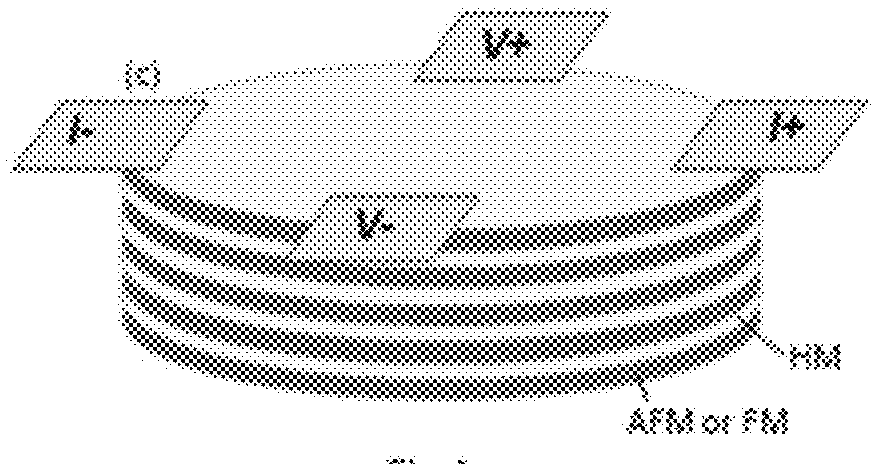
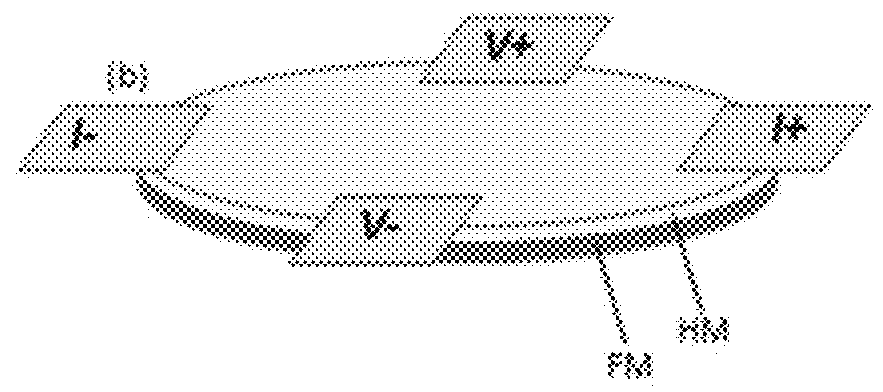
[0083]FIG. 4 is a schematic drawing comparing an AMR sensor with soft adjacent layer biasing (FIG. 4(a)) and an AMR sensor with barber pole biasing (FIG. 4(b) with a SMR / AMR sensor with SOT-biasing (FIG. 4(c)). The conventional soft-adjacent layer (SAL) transverse bias scheme shown in FIG. 4(a) comprises a SAL is made of a soft ferromagnetic material. The SAL is formed into a multilayer structure comprising a sensing layer (MR) with a thin insulating spacer separating the SAL and the sensing layer. Most of the current flows through the sensing layer. The magnetic field induced by the sensing current magnetizes and saturates the SAL in one direction (pointing upward in FIG. 4 (a). The fringe field thus generated, in turn, provides a transverse bias to the sensing layer. The bias angle is set by the combined effects of the thickness and magnetization of each of the MR and the SAL, and is fine-tuned by adjusting the current.

[0084]In the barber pole biasing arrangement sh...

example 3

Semi-Transparent AMR / SMR Sensors

[0088]This example describes semitransparent anisotropic and spin Hall magnetoresistance (MR) sensors with a transmittance exceeding 50% in the visible range. The key to achieving semitransparency is the use of spin-orbit torque (SOT) effective field for transverse bias which significantly reduces the total thickness of the sensor, down to 3-4 nm.

[0089]The NiFe / Pt bilayers were deposited on quartz substrates with the NiFe layer deposited first by e-beam evaporation and followed by the deposition of Pt using DC magnetron sputtering. Both layers were deposited in a multi-chamber system at a base pressure below 3×10⁻⁸ Torr without breaking the vacuum. An in-plane field of ˜500 Oe was applied during the deposition to induce a uniaxial anisotropy for the magnetic film. Before patterning into sensor elements, thickness optimization was carried out on coupon films by characterizing both the optical transmittance and magnetic properties.

[0090]FIG. 5(c) shows ...


PUM


Abstract

The invention relates to magnetic sensor comprising a sensor element that is able to generate a spin-orbit torque (SOT). The SOT acts as a transverse bias field to set a proper working point for the sensor and so ensure that it responds linearly to an external field with maximized sensitivity. It also functions as a longitudinal bias field to suppress domain wall nucleation and propagation. The use of SOT effective field for biasing not only simplifies the sensor structure but also makes it possible to make an ultrathin and semi-transparent magnetic sensor.

Description

CROSS-REFERENCE TO RELATED APPLICATION[0001]This application claims the benefit of Singapore Patent Application No. 10201608762Y filed Oct. 19, 2016, the contents of which are incorporated herein, in its entirety, by reference.FIELD[0002]The current invention relates to a magnetic sensor and to a sensor element for use in a magnetic sensor.BACKGROUND[0003]The listing or discussion of an apparently prior-published document in this specification should not necessarily be taken as an acknowledgement that the document is part of the state of the art or is common general knowledge.[0004]Various types of thin film magnetic sensors have been developed in the last two decades for use in the hard disk industry. These include anisotropic magnetoresistance (AMR) sensors, giant magnetoresistance (GMR) sensors, spin-valve (SV) sensors, magnetic tunnel junction (MTJ) sensors, and planar Hall Effect (PHE) sensors. The AMR effect has its origin in spin-orbit coupling (SOC), which results in anisotr...

Claims


Application Information

Patent Timeline
IPC IPC(8): G01R33/06
CPCG01R33/06G01R33/093
Inventor WU, YIHONGXU, YANJUNLUO, ZIYANYANG, YUMENG
Owner NAT UNIV OF SINGAPORE
Why Eureka
Try Eureka