Method of Assembly of Electrochemical Cells for High Temperature Applications

a high temperature application and cell technology, applied in the field of electrochemical devices, can solve the problems of terminal addition, difficult and expensive stacked into the housing, and too large cells for today's printed circuit boards, and achieve the effect of easy construction and high conductivity

Inactive Publication Date: 2018-04-19
VENKATESWARAN SAGAR +1
View PDF0 Cites 15 Cited by
  • Summary
  • Abstract
  • Description
  • Claims
  • Application Information

AI Technical Summary

Benefits of technology

[0008]Now it has been found, that much easier construction and methods of assembly of heat resistant micro-cells having high conductivity can be made by coating the cells electrode's materials with water based binder, in air, on pretreated aluminum or copper micro-grids' collectors without an electrolyte in the coating. The housing of the cell may be similar to the housing of Watanabe, and may have the metalized inside bottom and the top rim, and the metal lid. The electrodes of the invention are different and have long terminal tabs as an extension of the grid collectors.

Problems solved by technology

However, these cells are too large for today's printed circuit boards with micro components being soldered to them by wave soldering method, which requires passing the printed board with the micro-components like ultracapacitors through a furnace at high temperature to melt the solder (like 200-230° C.
), and they need to have terminals added, which is expensive.
Method of the prior art cell assembly is as follows: Due to the moisture sensitivity of the electrolyte / salts, the positive and negative electrodes with separator between them must be fabricated and stacked into the housing under inert atmosphere which is both difficult and expensive.
Each electrode layer and the separator layer are already activated by and contain an electrolyte before assembly, which prevents a good conductive contacts of wet electrodes with the collectors, and thus has a poor conductivity.
The metal lid is electrically connected and sealed to the metalized rim all around by brazing, which is expensive and cumbersome, and may thus create an imperfect seal.
Also, the brazing solder melting temperature is higher than the electrolyte boiling point temperature, which may damage the electrolyte and thus cause the cell failure.

Method used


Image

  • Method of Assembly of Electrochemical Cells for High Temperature Applications
  • Method of Assembly of Electrochemical Cells for High Temperature Applications
  • Method of Assembly of Electrochemical Cells for High Temperature Applications

Examples


Embodiment Construction

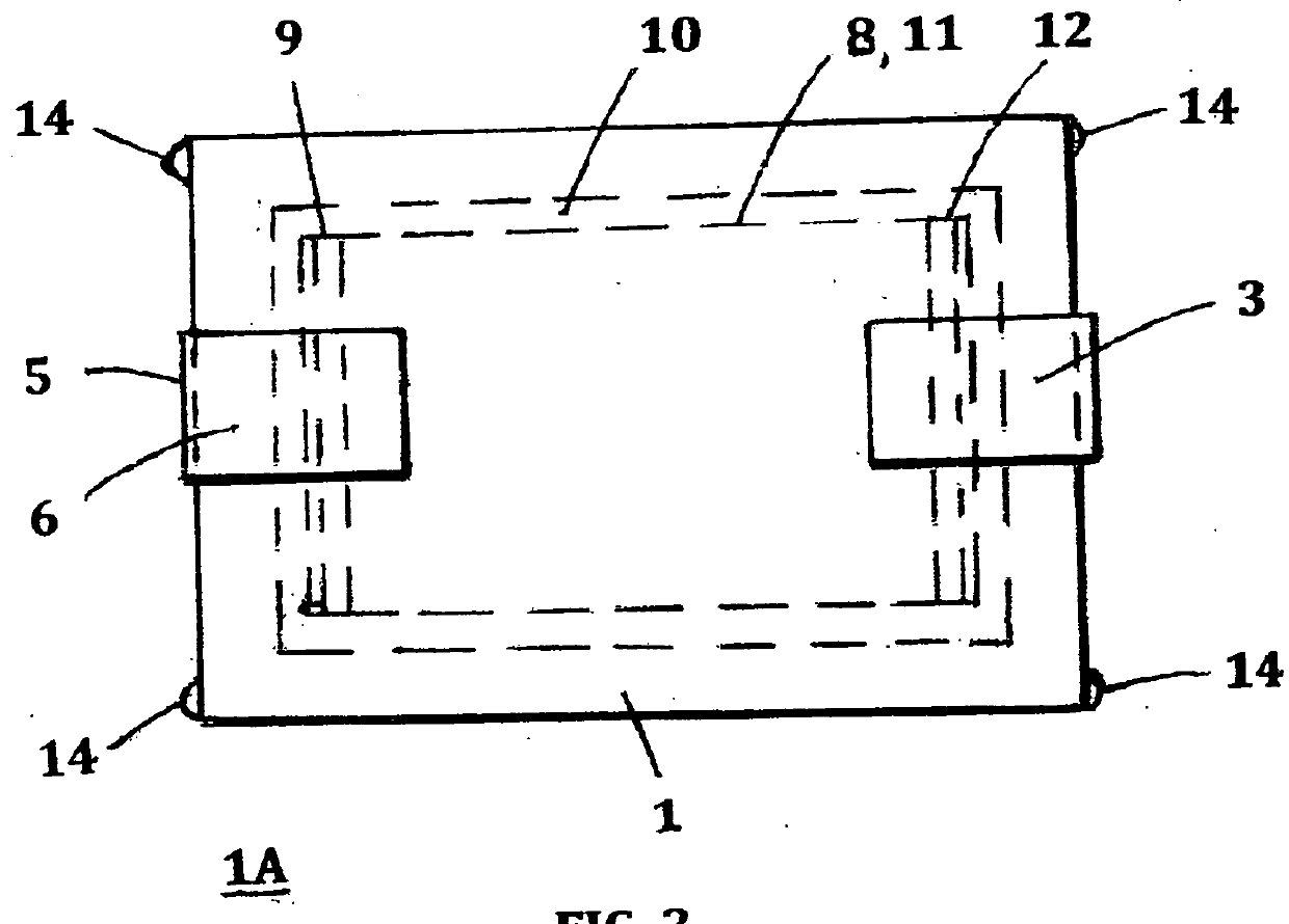
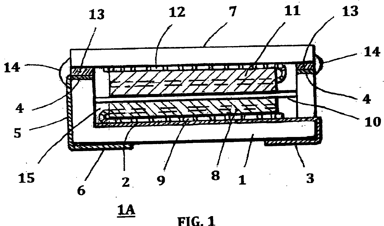
[0035]When referring to the preferred embodiments, certain terminology will be utilized for the sake of clarity. Use of such terminology is intended to encompass not only the described embodiments, but also technical equivalents, which operate and function in substantially the same way to bring about the same result. Referring now in more detail and particularly to FIGS. 1 and 2, which is one embodiment of the invention, showing cross-sectional and bottom view of a non-aqueous, high temperature cell 1A like ultracapacitor, asymmetric ultracapacitor, or lithium ion cell, which comprises:

[0036]Preferably electrically insulating ceramic, glass, or high temperature resistant polymer, square pan shaped housing 1, with metalized, preferably aluminum inside bottom layer 2, electrically connected to metalized positive terminal 3, on the outside bottom of the pan housing 1; metalized rim 4, all around the top of the housing 1; metalized connector 5, connecting the rim 4 with metalized negati...


PUM

PropertyMeasurementUnit
temperatureaaaaaaaaaa
boiling pointaaaaaaaaaa
heat resistantaaaaaaaaaa

Abstract

Heat resistant, highly conductive electrochemical cells for high temperature applications and methods of their assembly are described herein. The cells have at least two electrodes and at least one separator enclosed in heat resistant ceramic enclosure with metalized terminals on its bottom. Methods of the electrodes' tabs welding to inside connectors and the electrodes' coating are also disclosed. The resulting cells are solderable to circuit boards or various circuits.

Description

CROSS REFERENCE TO RELATED DOCUMENTS[0001]This Application is a continuation in part of the Application of Sagar Venkateswaran and Franciscus X. Pratiktohadi Ser. No. 15,330,120 filed on Aug. 10, 2016, and entitled “Electrochemical Cells Construction and Packaging for High Temperature Applications”.BACKGROUND OF THE INVENTIONField of the Invention[0002]This invention pertains to electrochemical devices, such as ultracapacitors and lithium battery cells, for high temperature processing and applications.Description of Prior Art[0003]Prior art high temperature electrochemical cells, such as ultracapacitors and lithium battery cells, are used mostly as a memory back up power of semiconductors, and are usually enclosed in a metal casing of a coin shape, having two shells crimped together with an insulating gasket there between. Each shell is in contact with one electrode. The cells are activated by non-aqueous, high temperature electrolyte before crimping. However, these cells are too la...

Claims


Application Information

Patent Timeline
Patent Type & Authority Applications(United States)
IPC IPC(8): H01G11/86H01M10/0525H01M10/0585H01M10/04H01M2/08H01M4/04B23K11/00B23K26/22B23K20/10H01G11/78H01G11/74H01G11/66H01G11/52H01G11/24H01G11/58H01M50/193
CPCH01G11/86B23K2201/36H01M10/0585H01M10/0468H01M2/08H01M4/0416H01M4/0409H01M4/0411B23K11/002B23K26/22B23K20/10H01G11/78H01G11/74H01G11/66H01G11/52H01G11/24H01G11/58B23K2203/08H01M10/0525B23K11/0026B23K11/115H01G11/72H01G11/76H01G11/82H01G11/84B23K2103/10B23K2101/36B23K2103/08Y02E60/10H01M50/138Y02P70/50H01M50/193
Inventor VENKATESWARAN, SAGARPRATIKTOHADI, FRANCISCUS X.
Owner VENKATESWARAN SAGAR
Why Eureka
Try Eureka