
Combined Power and Communications Cable

a technology of communications cables and power cables, applied in the direction of power cables, cables, plastic/resin/waxes insulators, etc., can solve the problems of increased manufacturing costs of additional materials, limited availability of connectors, and increased complexity of connectors, so as to reduce cross section, reduce cross section, and improve handling

Active Publication Date: 2018-05-31
ROCKWELL AUTOMATION TECH
View PDF5 Cites 5 Cited by
  • Summary
  • Abstract
  • Description
  • Claims
  • Application Information

AI Technical Summary

Benefits of technology

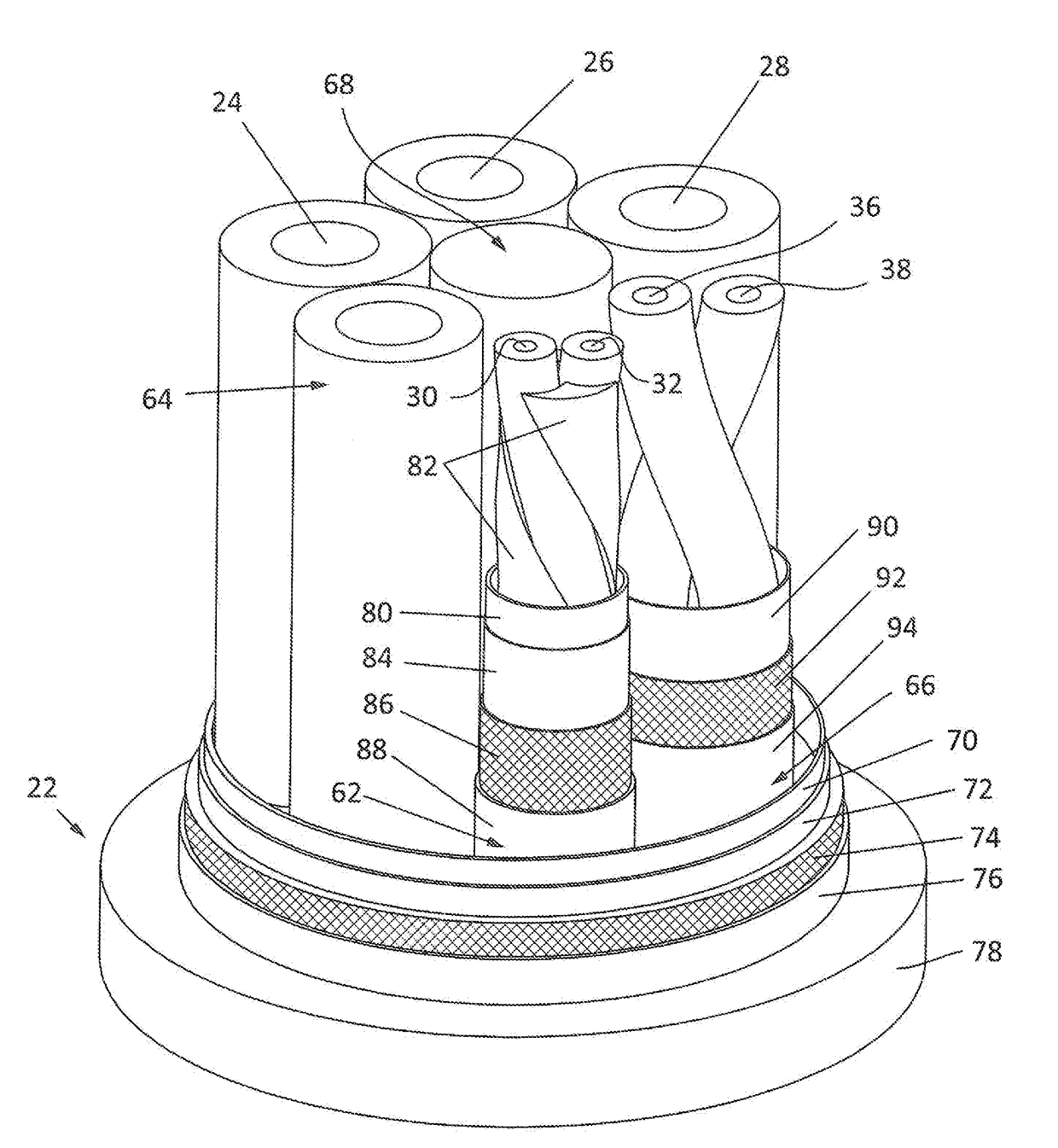
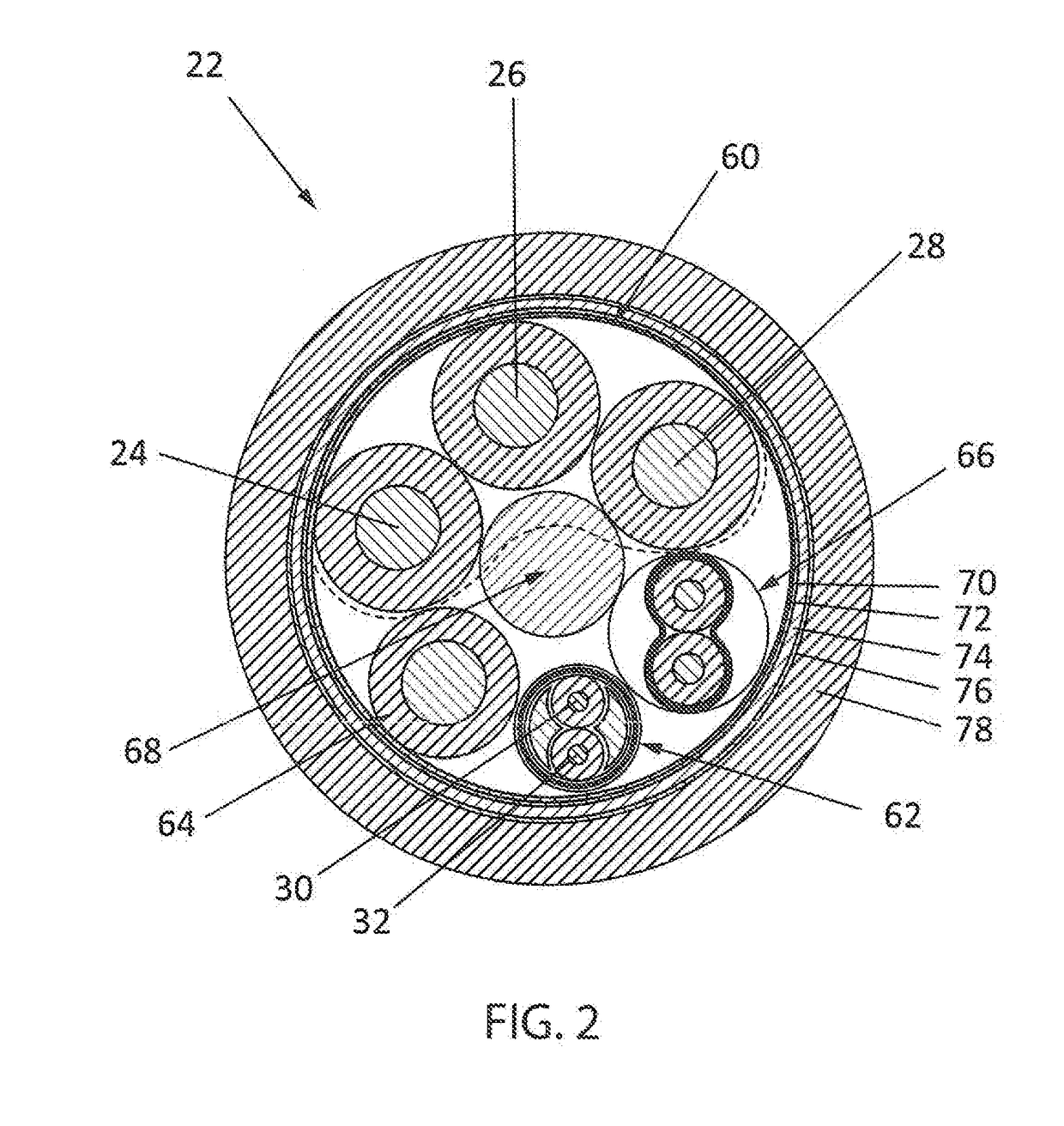
This patent describes an improved cable design that separates high voltage, noisy power lines from low voltage, noise-susceptible data lines to minimize interference and distortion. The cable has a smaller cross section, reducing handling difficulties, and includes a communication subassembly and a motor control brake subassembly for power delivery and control. The cable is designed with low dielectric constant insulation materials and copper braid to minimize voltage spikes and heating. The cable has a controlled field concentration and a quiet area for maximum signal quality and minimal signal distortion. The invention reduces crosstalk, interference, and distributor complexity while improving cable performance and handling.

Problems solved by technology

Larger cable cross sections can present several drawbacks, such as: smaller bend radius; increased manufacturing costs for additional material usage; increased complexity for connectors; limited availability for connectors; limited availability of compatible units; and / or increased distortion of data signals.
Moreover, by placing a communication link in a same core and under a same electrical braid as noisy power delivery conductors (which may be used, for example, to connect switching Insulated-Gate Bipolar Transistors (“IGBT's”) for motor stator windings), the communication links can be increasingly susceptible to signal distortion.

Method used


Image

  • Combined Power and Communications Cable
  • Combined Power and Communications Cable
  • Combined Power and Communications Cable

Examples


Embodiment Construction

[0023]One or more specific embodiments of the present invention will be described below. It is specifically intended that the present invention not be limited to the embodiments and illustrations contained herein, but include modified forms of those embodiments including portions of the embodiments and combinations of elements of different embodiments as come within the scope of the following claims. It should be appreciated that in the development of any such actual implementation, as in any engineering or design project, numerous implementation-specific decisions must be made to achieve the developers' specific goals, such as compliance with system-related and business related constraints, which may vary from one implementation to another. Moreover, it should be appreciated that such a development effort might be complex and time consuming, but would nevertheless be a routine undertaking of design, fabrication, and manufacture for those of ordinary skill having the benefit of this...


PUM

PropertyMeasurementUnit
poweraaaaaaaaaa
electric poweraaaaaaaaaa
three phase electric poweraaaaaaaaaa

Abstract

Aspects of the present invention provide an improved cable having a reduced cross section while continuing to provide high voltage (noisy) power signals alongside low voltage (noise-susceptible) data signals. The improved cable can be used for power delivery and communications between a motor and a drive in an industrial control system. The reduced cross section advantageously improves handling. By providing separate groups between a group delivering the power signals and a group providing the data signals, thereby enforcing a physical separation, and by twisting together individual conductors of the group delivering the power signals with the group providing the data signals and the groups providing the separation, the reduced cross section can be achieved while continuing to minimize noise and interference onto the data signals due to the power signals.

Description

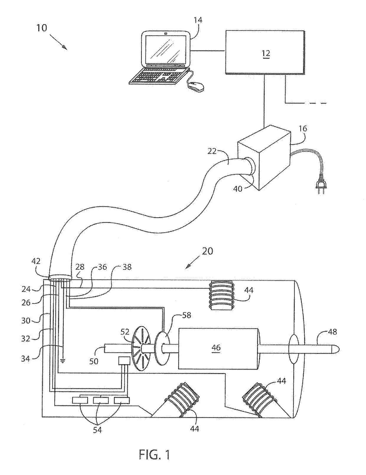
BACKGROUND OF THE INVENTION[0001]The present invention relates to combined power and communications cables and, in particular, to combined power and communications cabling for use in industrial control systems.[0002]Industrial controllers are specialized computer systems used for the control of industrial processes or machinery, for example, in a factory environment. Industrial controllers typically control numerous modules via specialized control networks for accomplishing different tasks in the industrial system. One such module may be a variable frequency drive (“VFD”) unit, which, in turn, may deliver power to, communicate with and / or control a motor. In industrial applications, motors may be used to affect a variety of motions in the industrial process. For example, motors may be operated at continuous or variable speeds, such as for turning the blades of a fan or the rollers of an assembly line at constant or variable speeds at different times, or may be used to precisely cont...

Claims


Application Information

Patent Timeline
Patent Type & Authority Applications(United States)
IPC IPC(8): H01B9/00H01B13/02H01B9/02H02K11/00H02K11/33H02K11/01
CPCH01B9/003H01B13/02H02K11/01H02K11/0094H02K11/33H01B9/02H01B3/30H01B7/04H02K11/21H02K11/25
Inventor SIDLYAREVICH, TIMOTHY P.
Owner ROCKWELL AUTOMATION TECH
Learn More